Help with substituting through hole with SMD

GroupDIY Audio Forum

Help Support GroupDIY Audio Forum:

This site may earn a commission from merchant affiliate links, including eBay, Amazon, and others.

sonolink

Well-known member
Joined
Feb 15, 2010
Messages
1,373
Location
London-Madrid
Hi everybody,

I'm trying to "convert" a through hole layout to SMD and don't know what footprint to use with some components in a PSU. Could someone advise me please?
This is the PSU schem:
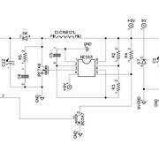

I'll be substituting resistors and caps with 0805 SMD footprint when possible (not the big electrolytics, of course). The components I don't know what hand solderable SMD footprint to use with are the following:

-100uH inductor
-7806 Voltage Regulator
-NE555 clock
-50mA self resetting polyfuse
-IRF740

Also, does anyone know what I could use to substitute these, please? They're for a cabsim.
BC547, BC337, BC327, TL072

Thanks a lot for your time and help
Cheers
Sono
 
Checking the datasheets of those components will likely reveal the SMD versions of each (where applicable). The inductor will likely depend on what sort of currents it's supposed to be used with. The following link may or may not help with that (in case the preexisting design doesn't specify any current rating):

http://schmidt-walter-schaltnetzteile.de/smps_e/aww_smps_e.html
You could then browse through Mouser's or Digikey's inventory to see what sort of footprints to expect, for the respective ratings. You can use the same logic to see what SMD mosfets can be found, with similar ratings to the IRF740, as well as for the bipolar transistors.

Depending on what CAD package you're using (if any), that should have a TL072 in an SMD package as well. Or any other dual opamp - hooray for standards.

I have great objections on the layout of that schematic though, but that's just me and my "ocd" :LOL: Or just "best (engineering) practices"...
 
Thanks for your reply Khron. TBH the only thing I know is that I plug. 9v/2A PSU into the input of that circuit and I get 250vdc and 6vdc on the other ends.

Your link is very interesting and I'm all willing to learn but I'm not an EE and can't make out how to use it...

I'm using Diptrace, and it has libraries but I kind of get a bit lost since I'm new to SMS. Also, some of the Through hole components are very old and I can't find a direct equivalent in SMD.

This circuit is quite popular among guitar tube pedal builders. I was hoping that someone would be more acquainted with it and SMD.

Thanks anyway for your time and help :)

Cheers
Sono
 
250V DC, and 6V - sounds like a supply vor a tube-based device then. How many triodes are used? That's to be able to gauge how much current the high-voltage side would need to supply.

The calculator in the link above is quite simple to use, actually, and it even auto-suggests some things.

Vin_min, say 7v
Vin_max, 12v
Vin for calculations, the nominal 9v
Vout, the 250v you mentioned
Iout, i just asked about above, but let's say 10mA (0.01A, ignoring the "V" typo above the text box there)
Frequency... Well, that's a toughie, since there are no component values in that schematic. But let's spitball a 50kHz there.

Pressing "Calculate" gets us a suggestion of just under 1mH for the inductor, and the second graph shows the average inductor current as 0.28A. An 0.5A rating should suffice.

Buuuuut if we manually force it to use a 100uH inductor (untick "proposal" and type "100E-6" there), we still end up with a 0.28A average inductor current, just a higher peak. If you want to exaggerate, look for a 1A-rated inductor.
 
With those values, the 555's operating at about 31kHz. Doesn't change things massively, apart from the peak inductor current.
 
That current rating is for the inductor only.

For the rest, read through my first reply here again.
 
Ok. I'll try my best but I'm just unsure I will completely understand how to choose one component over another :)
In any case I appreciate your the guidance ;)
Cheers
Sono
 
6V linear regulator? that might be tough to find these days.

you can probably go with a SOT-223 footprint AMS1117-ADJ (max output current 0.8A), a cheap and cheerful clone of TLV1117-ADJ, however you will have to add two 1% thick film chip resistors to program the adjustable output voltage to 6V. Calculation for the resistor values is in the datasheet.
https://www.ti.com › lit › ds › symlink › tlv1117.pdf

SOT-223 is very easy to solder by hand.

As for IRF740, I recommend you stick to the original TO-220 footprint with heatsink and all, because getting an SMD alternative that can output high current, usually mean the solder pad on the PCB will be used as a heatsink. Tough bitch to solder and remove later on if you don't have a reflow station.

BC327, BC337, BC547 (or BC847) are still in production. Are you looking for SMD version of these parts as well? They are available in SOT-23 footprint.

TL072, NE555 = SOP-8/SOIC-8 standard footprint, not the wide one.

Hope that helps.
 
6V linear regulator? that might be tough to find these days.

you can probably go with a SOT-223 footprint AMS1117-ADJ (max output current 0.8A), a cheap and cheerful clone of TLV1117-ADJ, however you will have to add two 1% thick film chip resistors to program the adjustable output voltage to 6V. Calculation for the resistor values is in the datasheet.
https://www.ti.com › lit › ds › symlink › tlv1117.pdf

SOT-223 is very easy to solder by hand.
What about this one? Is TO-252-3 easy to solder by hand?

https://www.mouser.es/ProductDetail/ROHM-Semiconductor/BA7806FP-E2?qs=Bakm8ERcljrjsjvfDXHyKw==
Cheers
Sono
 
Yup, that package is bigger than SOT-223.

Lucky you for being able to shop from Mouser. I used to be able to do that too before Covid, but now, with shipping fee plus the new import tax rule recently made by the government of this country where I live has made it almost impossible to buy parts from everywhere else except China, because they will end up costing a lot of money.

Thanks to that, counterfeit parts are abundant here. I can't even buy common electrolytic capacitors anymore. I was looking at 22mm x 30mm 105C 4700uF/35V for my Genelec, and only found fake Chemicon, Nichicon and Rubycon. Geez.
 
Last edited:
Keep in mind that some of those parts have significant DC across them (for example, the first feedback resistor R7), and a common voltage specification for 0805 is roughly 50-100V. You either need to a) move up to bigger package like 1206, or b) use several 0805's in series.

Also, finding high voltage, low ESR caps in SMD can be an issue (critical for C22), so again you might need to break C22 into multiple caps in parallel.
 
Keep in mind that some of those parts have significant DC across them (for example, the first feedback resistor R7), and a common voltage specification for 0805 is roughly 50-100V. You either need to a) move up to bigger package like 1206, or b) use several 0805's in series.

Thanks for chiming in Matador ;)

Excuse my probably dumb and elemental question: two 1w resistors in series are equivalent to one 2w?

Also, finding high voltage, low ESR caps in SMD can be an issue (critical for C22), so again you might need to break C22 into multiple caps in parallel.

I was thinking of subbing all caps for C0G, NP0 or X7Rs and when I can't get enough capacitance/power (especially with big electrolytics in the PSU) I'd stick to TH lytics.

But C22 is rated for 25v isn't it? Why do you say it needs high voltage rating?

Cheers
Sono
 
Excuse my probably dumb and elemental question: two 1w resistors in series are equivalent to one 2w?
If they are of identical value, yes. Power being shared equally by both resistors.
Now if you had 1800 ohms in series with 200 ohms for making 2000, the power received by the 1.8k would be 9 times that in the 200.
But C22 is rated for 25v isn't it? Why do you say it needs high voltage rating?
There are no values in this schemo, but if the HV output is 250V, then C22 must be rated at least at 250V continuous
 

Latest posts

Back
Top