How to test a filter ?

GroupDIY Audio Forum

Help Support GroupDIY Audio Forum:

This site may earn a commission from merchant affiliate links, including eBay, Amazon, and others.

Freq Band

Well-known member
GDIY Supporter
Joined
Jan 5, 2006
Messages
608
Location
Electra City
I've been getting s slew of used gear in recently.

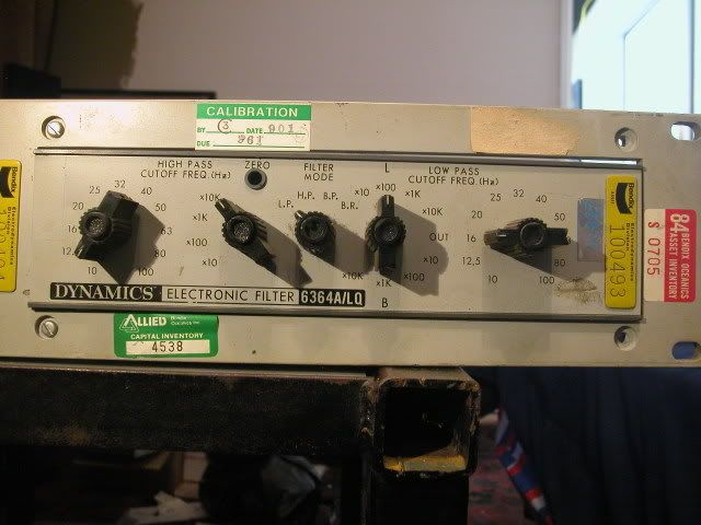
Here I have a dual electronic filter by Dynamics Electronics Products Inc. (Chatsworth, CA)....model 6364A/LQ

DSCN2340.jpg


more pics:
http://i5.photobucket.com/albums/y177/Midiot/DSCN2337.jpg
http://i5.photobucket.com/albums/y177/Midiot/DSCN2334.jpg

I am hoping it might be swell for audio use...EQ.

What is the best way to test it?

I don't have a hardware spectrum analyzer.
But I DO have software versions....my RME soundcard comes with a Spectral Analyser (DigiCheck), and Wavelab has one too, an FFT version.

I don't know yet if the filter's output needs attenuation.
What is the ideal signal to put through this filter?
I have some files on the 'puter ...

Pink Noise,
UNcorrelated Pink (20 dBFS)
Multi-tone with 1kHZ spacing
Multi-tone w/ 500 kHZ spacing
Blue, White, Brown, Violet noises,
and of course an outboard funct. gen.

Thanks,

=FB=

(Dynamics was bought by Bendix/Allied in the early 80's I believe, and this unit is from the late 70's)
 
Well, to test if it works at all, I ran a sine wave through it, to a scope.
That seemed ok.
I then ran some pink noise through it and listened over some speakers, and it seems to do what it should. But the ultra dirty switches had my speakers about to pop and explode, so I ended the tests until I clean the switch contacts. They are soldered to the boards, that makes it difficult.

The other down side is that it is switched values, not pots. Might be good for special effects, or test usage.
I'd love to know the slope amounts.

=FB=
 
More specifically:
(and the question formated differently)

How do determine the slope per octave (12 dB, 24 dB, 48 dB, ...) of a filter?

This would require feeding the filter a _______ type signal, at a level of ______ .

The output of the filter is sent to a _________ .


The filter's Lowpass settings should be at _______________ .

The filter's highpass settings should be at _______________ .

The equation for determining the filter's slope (at _______ ) would be : ________________ .

On a spectrum analyzer, the slope would obvious by looking at ____________________ .

From this information, you can also determine the filter's _______________ .
---------------------------------------------------------------------------------------

I do not posess the knowledge to make sense of calculations such as this
(first order opamp compensation I think):
Lab8(F10.gif


But I do understand this :
"The slope of a filter
defines the rate at which the filter response falls beyond the cutoff frequency. This is usually
defined in dB/octave and common slopes are 6, 12, 18, and 24 dB/octave. It is common for the
terms “filter slope” and “filter order” to be interchanged with one another. An increase in filter
order refers to a 6dB/octave increase in slope. Very simply, a 1st order filter refers to a 6dB/octave
slope, 2nd order to a 12dB/octave slope and so on. For example, a 24dB/octave Butterworth filter is
the same as a 4th order Butterworth filter."


and a filter glossary:
http://www.freqdev.com/guide/DgtlFltrDsgnGd.pdf

=FB=
 
Em... testing db/octave is as simple as picking a frequency in the rejection band, then picking a signal of DOUBLE frequency (for a LPF) or HALF (for a HPF) and measuring how much LOWER the signal is than the first measurement signal.

If it's -4dB on the first freq and -10 on the second, that's a 6dB/8ve rolloff etc.

I didn't even read your post in detail, it looked like it would make my head ache, there's no reason to over-think this...

Keith
 
Smart-a$$ answer to all the above questions:
Plot the freq response on an AP...

Sorry that is no help...but Keef's instruction should work fine for general determination of the slope.

Peace!
 
I don't think that cleaning switches may help: most probably they conduct some DC current...
 
I air blasted the switch decks, and flooded them with some spray contact cleaner, then treated them with some Caig contact lubricant.
This fixed 90% of the problem.
But when I "jiggle" one of the knobs, I still get some anomalies.

=FB=
 

Latest posts

Back
Top