Inductance measurement problem

GroupDIY Audio Forum

Help Support GroupDIY Audio Forum:

This site may earn a commission from merchant affiliate links, including eBay, Amazon, and others.

DaveP

Well-known member
Joined
Nov 8, 2005
Messages
3,037
Location
France
Happy New Year to everyone,

My LCR meter only goes up to 20H like most of them do, so to test the primary of an Edcor XSM15k 600 TX I needed another method.  The most straight forward method, that is popular on the web, is to put a series resistor in line with the inductance with a probe from each channel of a scope either side.  You then vary the frequency of the sig gen until one trace is exactly 50% of the other.  My scope has a built-in frequency counter so it seemed like a good test.  Using this formula  H= XL/2pi x f you can find the inductance when the reactance matches the series resistor, what could go wrong?

I decided to do the test with several different resistors to check the result, lucky I did because there is obviously another factor to take into account, here's the data:-


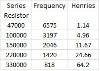
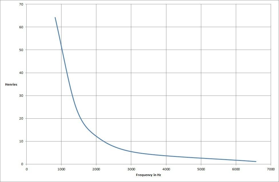
As you can see, the result you get depends on  the test resistor used, so there must be a correction factor for phase to compensate the data, there is no mention of this in the methods shown on you tube etc.

Does anyone know how to do this?  Sines? Cosines?  I think I can remember them OK.
Mumble mumble current lags voltage by 90 degrees mumble mumble :-\

Best
DaveP
 
DaveP said:
....what could go wrong....

The answers are here:

http://www.edn.com/design/test-and-measurement/4363759/Circuit-measures-capacitance-or-inductance

eq 15

and here:

http://www.tek.com/document/application-note/capacitance-and-inductance-measurements-using-oscilloscope-and-function-ge


Thanks for trying to help but the first site just adds root 3 or 1.732 to the divisor without correcting anything.

The second link mentions the phase angle but does not show how that is calculated/found so no help there either.  I think they are using a much more sophisticated scope than mine which can do averages and various other calculations.

DaveP
 
Iron-core inductance goes down with frequency because eddy-currents throw-out the magnetic field so less iron is working at higher frequency.

What do you *really* want to know??

Probably Bass Response.

And it is very unlikely you want a bass-limit of 818Hz, much less 6KHz; nor that you should be testing with resistors ~~10X the nominal 15K.

Pick your target frequency.

Series circuit, R and L. Measure voltage across L.

You want -3dB, NOT 50:50.

Vary R so that -3dB happens at your desired bass limit.

If it  hits that, it will "support" all higher frequencies, even though inductance is not rising as fast as simple coil theory says.
 
DaveP said:
Happy New Year to everyone,

My LCR meter only goes up to 20H like most of them do, so to test the primary of an Edcor XSM15k 600 TX I needed another method.  The most straight forward method, that is popular on the web, is to put a series resistor in line with the inductance with a probe from each channel of a scope either side.  You then vary the frequency of the sig gen until one trace is exactly 50% of the other.  My scope has a built-in frequency counter so it seemed like a good test.  Using this formula  H= XL/2pi x f you can find the inductance when the reactance matches the series resistor, what could go wrong?
Except it's 70.7% (-3dB) and 45° phase shift, and the formula works well when the DCR of the inductor is << than its reactance, so you need to adjust the frequency that allows L.omega>>Rdc and also ensure that Rloss doesn't play havoc.
As you know, a pure inductor sees its impedance increasing towards infinity, but a real one with losses reaches a plateau and/or a peak (this one due to parasitic capacitance).
That's why you need to measure the DCR and make at least one high frequency meaurement in order to evaluate the impact on impedance.
 
PRR,

What I really want to know is if I can measure inductance with  a scope, sig gen and freq counter.  Various sites on the web say you can but now I realise they are giving out false info, I hadn't realised that before and yes I would like to be able to test for bass response.  Edcor gives inductance on some transformers but not all.

Witness,
https://www.youtube.com/watch?v=01Ebd6eR7Lw, 
http://www.wikihow.com/Measure-Inductance
http://www.dos4ever.com/inductor/inductor.html

I don't get why -3dB is better than -6dB?

DCR of the TX primary is 808 ohms by the way.

CJ,

I can put 10V at 20Hz across the TX but I can't measure the current, my LCR won't register it.

I have even tried putting a known cap in series and then in parallel but I can't detect any frequency which might be at maximum or minimum, by this method either

Abbey,

From what most of you are saying, it seems to me that Inductance can't really be measured by a standard test, because there are too many other variables/parasitics/anomalies to screw up the measurement. .

The whole subject suffers from the  Wikipedia Paradox, to wit: If you can understand the article, you don't need to be reading it. Articles like this one may be technically correct, but are not written at a level that the layperson can understand.

Sounds a lot like Catch 22 to me ???
DaveP


PRR's method.

Frequency 40Hz, variable pot in series with primary and with pot on zero there is 10Vac across the primary.  By adjusting the pot I can get 7.07Vac across the primary with the pot on 80.9K.  Does this represent the reactance?

DaveP
 
DaveP said:
What I really want to know is if I can measure inductance with  a scope, sig gen and freq counter. 
Yes!
Various sites on the web say you can but now I realise they are giving out false info, I hadn't realised that before and yes I would like to be able to test for bass response.  Edcor gives inductance on some transformers but not all.

Witness,
https://www.youtube.com/watch?v=01Ebd6eR7Lw, 
This guy does not understand that inductors shift phase by 90°, so the calculation is correct on wrong physics. He just stupidly applies a formula he found on the internet. Why does he endeavours to teach courses when he hasn't grasped the gist of it? He mixes kHz and MHz...Jerk! 
http://www.wikihow.com/Measure-Inductance
That one is more correct, in the sense the physics are correct but the math are unduly complicated. If it was for better accuracy, I would accept it, but they don't take into account the fact that real inductors are not perfect.
http://www.dos4ever.com/inductor/inductor.html
This one uses a method that loads the output of a 50 ohms generator; it means that it would give about 5% accuracy for inductors that have less than 2.5 ohms DCR. Appropriate for RF and SMPS inductors, but not for usual low-level audio.
Using a more appropriate audio generator with 600r output Z, that would give good accuracy for inductors with less than 30 ohms DCR. That would be appropriate for maybe half the occurences, not for mic input xfmrs, much less for tube output xfmrs, most of the EQ inductors...
I don't get why -3dB is better than -6dB?
It's where the combination of signal amplitude and measurement sensitivity is optimum. In addition, the formula is much simpler: L=R/2pi.F
DCR of the TX primary is 808 ohms by the way.
that has to be considered in the context of the estimated impedance. If it is much smaller (about 10 times smaller), it doesn't change much the result. If it is a significant fraction of teh estimated Z, tehn it's more complicated. You have to deal with 2nd-degree equations that are not very difficult per se but have fastidiously long terms; it's too easy to get lost. In that case, I would suggest using a simulation software and do a trial-and-error approach to refine the numbers.
From what most of you are saying, it seems to me that Inductance can't really be measured by a standard test, because there are too many other variables/parasitics/anomalies to screw up the measurement. .
Damn! Second time in one day that I'm caught at pontificating and making things appear more unfathomable than they actually are.
The method is right, but one has to know the limits and the effects of parasitics.
In particular, the internal impedance of the generator must be small in comparison with the estimated impedance.

BTW, there was a thread some time ago about this very subject, and I think we managed collectively to produce a better picture.
Finally, LF inductance of iron-core inductors/xfmrs depends very much on signal frequency level, so it's good to use for measurement a signal as close as possible to the intended, and a series resistor that is adjusted to attain the desired -3dB. In that respect, most LCR meters are utterly inadequate.
 
DaveP said:
PRR's method.

Frequency 40Hz, variable pot in series with primary and with pot on zero there is 10Vac across the primary.  By adjusting the pot I can get 7.07Vac across the primary with the pot on 80.9K.  Does this represent the reactance?

DaveP
Yes. And the earlier-quoted DCR of 808 ohms is negligible there, so the inductance computes at 322 H.
 
Iron-core coils are NOT simple beasts.

For coupling, what we want to know is: do they support our bass? (However you define "bass".)

CJ has his single-point 20Hz reference, which is appropriate when you cut-up hundreds of high-quality irons.

Myself I'm happy to know that loss on a low-price iron will be small at say 40Hz. I'd probably just nail the nominal 15K, sweep from 1KHz down. The drop at 40 or 50Hz is the goodness factor. I'd watch around 400Hz for wobble.

In this you should monitor the output. If it gets obviously distorted at low F, drop the level and start over. In many-many cases the "useful bass response" IS about distortion more than response levelness. You can take a $3 transformer, drive it with a power amp, and show "flat -3dB to below 50Hz". However the maximum output at 50Hz will be 1/10th the voltage it will pass at 500Hz. For $3 you only get promised a volt or so at 500Hz, so the operating level with 50Hz in the signal may be silly-low, -20dBm.

The 3dB 70% for X(L)=X(R) is very simple. An R=L series circuit is 3dB down at equality. Anybody saying that X(L)=X(R) makes half-voltage has not studied reactances. They phase-shift.

For resonating, iron-cores are frustrating because L will vary with level, also mechanical strain. L-C audio tanks usually need large air-gaps, the iron only used to reduce overall size, losses, and leakage from a totally air-core design.
 
> Frequency 40Hz, variable pot in series with primary and with pot on zero there is 10Vac across the primary.

Clarification: run F up to 800Hz or 1KHz, adjust for 10V. *Then* go down into the bass. (Zero-pot is not zero-Z; going well up from bass makes Z(L) much higher so we can ignore such minor points; also the ear will judge how 40Hz comes out compared-to midband level.)

(10V is reasonable in this case. For smaller iron or lower Z you use a lower voltage.)

> can get 7.07Vac across the primary with the pot on 80.9K.

With 81K source you get -3dB at 40Hz.

Then assuming your source is 15K (as Edcor suggests), your -3dB is probably nearer 8Hz.

Finding few-Hz small-signal response on high-level transformer is very normal. To have low THD in the 40-50Hz range (where it matters) you must have very low inductance shunting (the iron is not strained).

> DCR of the TX primary is 808 ohms

That sets a lowest-possible limit how much better the low-level response "could" be if you drive with a zero-Z source (heavy NFB and some power). We found 40Hz with 81K source. (Actually 82K including DCR.) With zero source and just the 808r in the way, response should shift *roughly* to 81,708/808 or 101 times lower, 0.4Hz. Note that your source's load is dropping close to 808 ohms, not the nominal 15K. Also the saturation voltage drops with frequency, so 10V at 40Hz clean may be 0.1V at 0.4Hz clean.

808 is 5.3% of nominal 15K. Primary transfers 94.7% of the power it gets. This would be very reasonable for this class and size of transformer. Assuming secondary DC loss is the same proportion, the power transformer efficiency loss is like 94.7%*94.7% or 0.897, 0.47dB. If this were "just a power transformer" we would cut cost with fewer turns of thinner wire on a smaller core-- at this size the wise (cheap) PT designer wants 20% loss. (The heat will dissipate, and the seller isn't paying the electric bill). But we want low THD and below power frequency, so a heftier design is wanted (if the market will pay). I think Edcor did well, at least on the low end.
 
Damn! Second time in one day that I'm caught at pontificating and making things appear more unfathomable than they actually are.

Abbey, that made me laugh, but don't be too hard on yourself, you have lots of us dimwits to deal with on a daily basis. :p

It's where the combination of signal amplitude and measurement sensitivity is optimum. In addition, the formula is much simpler: L=R/2pi.F

Ok, I get the root 3 deal but shouldn't root 3 figure in the formula?

DaveP
 
PRR,

Thanks for all that, I GET IT ;D

By the way I did search first thinking this might have been covered before, but I couldn't find anything.

Your method should be posted up somewhere for reference, I shall be copying and pasting it into a doc.

Best
DaveP

 
DaveP said:
I think they are using a much more sophisticated scope than mine which can do averages and various other calculations.

If your measuring frequency is low (usually below 1kHz), you don't need a scope, almost any DVM will be fine.  If you have two DVMs, just connect one on resistor, second on an serially connected inductor, and find resistor's value where both readings are equal.  That's XL value.
 
you probably want to measure the inductance of the transformer or choke or Pultec inductor or whatever in the same way as it is being used in the circuit,

you will not see a series resistor being used with too may transformers, in fact, engineers try to get DCR as low as possible for a variety of reasons,

inductance will follow the BH curve, these curves are a function of level, so you want to use a reasonable level to check inductance, this can be a problem with big audio transformers, we used to use a variac running off a big power source that had a freq control on it, the variac did not like 5 hz for very long, in fact, 10 hz was even a struggle for the poor thing, so you had to test quick before it rattled itself to death,

an HP tube sig gen is ideal for most audio inputs and outputs as the level goes up to about 25 volts and is driven by a big pair of power tubes, this means that the voltage will not fade even with low inductance, low DCR coils,

what about a Marshall OPT?  25 volts ain't gonna put you anywhere near the normal operating point of the transformer, so your Henries readings will be lower than normal as you will be on a part of the BH curve where the slope is more shallow which means you get less flux for a given excitation current, H is determined by amp-turns, well, turns stay the same, but amps go up with voltage, so you want H to be at the operating point of the Marshall amp, how do you do this? break one of the plate leads insert an ammeter, be careful of course, hook the sec up to a 1K resistor, this keeps the OPT from blowing up but does not falsify the current reading due to the speaker load dragging amps from the pri circuit,  measure the ac volts, divide by current, you have XL, from there it is easy to calculate H.

here is a screen shot of a spread sheet we use when trying to get a detailed idea of pri inductance,

it has corrections for DCR of the pri as well as phase shift due to DCR, Henries readings will be skewed the most at 5 to 10 Hz as DCR and XL start to merge, XL dropping because of the low freq.

you can also do a spreadsheet at a fixed freq and vary voltage level to see how the inductance changes with level and what the saturation point is,

speaking of saturation, watch your excitation level at 5 and 10 Hz, flux goes way up down there, so if you see a non linear increase in current, you are probaly hitting the core too hard, you can see that we drop the voltage sometimes at the lower freqs because of this (pic)

so throw away the resistor,  and the formulas along with it,  buy a DMM, use the AC Amps function, program a spreadsheet with Ohms Law and 2 pi fL, and you will be rockin,  listening tests are also good as the do away with the equipment and the formulas,  :D


Attachments

  • Henries.jpg
    Henries.jpg
    124.4 KB · Views: 34
abbey road d enfer said:
https://www.youtube.com/watch?v=01Ebd6eR7Lw, 
This guy does not understand that inductors shift phase by 90°, so the calculation is correct on wrong physics. He just stupidly applies a formula he found on the internet. Why does he endeavours to teach courses when he hasn't grasped the gist of it? He mixes kHz and MHz...Jerk!

http://www.wikihow.com/Measure-Inductance
That one is more correct, in the sense the physics are correct but the math are unduly complicated. If it was for better accuracy, I would accept it, but they don't take into account the fact that real inductors are not perfect.

Both links have reference to the article

http://daycounter.com/Articles/How-To-Measure-Inductance.phtml

with the error in the calculation.
 
Thank you for that spreadsheet CJ, that will help a lot of us with organizing.

Magnetism and inductance are two subjects I struggle with as the terms  sound alike and some symbols get reused making the confusion compound. You guys have done very well helping me understand more and more everyday.
 
moamps said:
Both links have reference to the article

http://daycounter.com/Articles/How-To-Measure-Inductance.phtml

with the error in the calculation.
There's no error in the calculation; sqrt2 applies for 0.707 voltage (equal voltage in the L and in the R but shifted pi/2).
And sqrt3 applies for 1/2 voltage in the L, which results in 0.866 (1/2.sqrt3) in the R.
Indeed, although the calculation is correct, the method is based on dubious understanding of the phenomena at play.
Additionally, the comment about "it is accurate in that calibration resistors can be found with tolerances in the 0.1% range" shows they have absolutely no understanding of basic metrology. The accuracy of reading an oscilloscope screen in the conditions of the experiment is at best 2% , and the parasitics at play (generator internal Z, series DCR, losses and stray capacitance of the inductor may very well account for 5-10% error.
It's known since ages that inductors cannot be manufactured with the same degree of repeatability than resistors and caps.
A designer knows that he must either accept inevitable deviations or provide means to correct them. In tuned circuits, it means either using a tunable core or tuning the capacitors.
The ultimate way of assessing an inductor is by measuring the circuit that has been designed around, at nominal operating conditions.
Other measurements only give a degree of confidence.
 
Back
Top