Is there an Altec 1612a mod for attack and release?

GroupDIY Audio Forum

Help Support GroupDIY Audio Forum:

This site may earn a commission from merchant affiliate links, including eBay, Amazon, and others.

dissonantstring

Well-known member
Joined
Jun 3, 2005
Messages
1,041
Location
san jose, ca.
hi guys,
a friend of mine asked me to look at an Altec 1612a limiter and see if it was possible to modify the attack and release times of this unit.  i have no experience with this unit, but i'd like to see if i can at least look into this for my friend.

here is a bad copy of the schematic (sorry) :-\:http://www.altecpro.com/pdfs/vintage/ElectronicsAndTransformers/signalProcessing/1612A%20Signal%20Processing%20Manual.pdf

from my understanding, the attack and release are set to slow/fast on a switch (J3) coming off of Q4 (mosfet).  i'm trying to understand the circuit better and get some hints as to what affects the attack and release timing in this circuit.
the end result to the mod would be a slower attack time and a faster release time (as requested from my friend).

any help or ideas are greatly appreciated. 
cheers,
grant


The schematic diagram is very difficult to read. But as far as I can see, R44 is the one to change if you want a slower attack time.
This resistor is shortened in the 'fast' position. Increasing the value will make the attack time slower.
 
hi RuudNL,
thank you very much for taking a look at the really bad schem.  i found a marginally better schematic, but it didn't help much either. 

i see what you talking about with the switching of R44 (10K).  maybe i'll have to experiment with a variable switch for different timing. 

does anyone know if changing R44 affects only the attack or both the attack and release in this circuit?  i'm guessing both, but my knowledge is rather lacking.

RuudNL thanks for taking the time and for the help!  very much appreciated.
kind regards,
grant
 
No, I don't think R44 will change attack and release times. IMHO this resistor will only change the attack time.
As far as I can see there is a resistor connected to the gate of a FET (Q4) of 3M3 (?) This resistor is connected to a point marked 'Release control'. This resistor must be responsible for the release time. But everything is very difficult to read!
Attack and release times are linear, if you double the resistor value, you double the attack or release time.
The capacitor in the timing circuit must have a low value (< 1 uF), but I can't read the values.
 
hi RuudNL,
thanks for the info on the 3M3 resistor (R24). 
would the timing circuit be the C/R coming off of the gate of Q4? 
(i read it as .47uF in series with a 22R to GND).

i'll do some experiments on the 10K attack and 3M3 release resistors when i get the unit.  you have been very helpful.
cheers,
grant
 
I've been looking at this in my knowledge quest for my 525 attack understanding.

from what I'm getting off the blurry picts..

Attack and Release of stock are one of the following based on switch settings:
Fast  A=10 Micro Second, R=0.8 Seconds
Slow A=33 Micro Second, R=2.8 Seconds

The Slow/Fast switch is 2 position and only has wires connected to the fast side.

When selected to mode Fast wires 4 to 5 are connected and wires 2 to 6 on J3 connector.

This looks like in Fast mode it grounds R24 putting it in Circuit and shorts out the 10K resistor.

http://www.cvs1.uklinux.net/cgi-bin/calculators/time_const.cgi
10K and 0.47uf =4.7ms (not micro)
3.3M and 0.47uf=1.5 seconds (which is 1/2 the slow setting of the release)

made correction to what I was trying to say,,
 
I've seen this before, that the calculation of the RC time did not match the manufacturers specification.
There is an explanation I think:

- It might be that the capacitor is charged from a higher voltage (=higher current) at the moment the limiting sets in, than later when the correct amount of limiting is already reached.
- It might be that 'zero' attenuation is already reached before the capacitor is completely discharged.

I still can't read the values, but you should play with the 10K and 3M3 resistors to change the attack/release times.

Success!!
 
hi guys,
good discussion.  (thanks for butting in kazper! - jk) :mad: ;D

like kazper, what led me to think about this mod a bit more was my curiosity of the timing circuits of the PM660 with the lolo-m's mod and also the sta-level recovery time mods (and comp circuits in general), so this has been very educational for me who understands very little of this stuff.

kazper said:
from what I'm getting off the blurry picts..

sorry about the bad scan of the schematic guys.  i'll try to find another one, but i think there really isn't a good copy of it on the web.  maybe some kind member will have a copy to scan and upload to the gmail account.

thanks for the learning guys! 
kindest regards,
grant
 
I know what your saying been beating my head against the wall all week long trying to figure out how they got the attack time of a stock 525 circuit. I can calculate the Release out and it's fairly close to values, but I'm way off with the attack.

I'm going to finish the 525's stock (no attack pot) and then measure with my scope and see whats going on there, then I'll adjust the values a bit to see what happens and compare them to my calculated ones.

Kaz

I should be at that point this week hopefully unless I'm missing some more parts... the story of my life!
 
thanks for your gracious help RuudNL!! (thumbs up!!) 

i have a much better understanding now of the components involved with modding the attack and release times.  i will need to experiment, but you've helped me understand the circuit better.  i know that simply changing the resistors will affect the fast/slow settings of the attack and release as set by the resistors and the switch configuration, but i may go as far as to separate the two controls or make them continuously variable (maybe).

thanks for heading me in the right direction RuudNL.  very much appreciated.
kindest regards,
grant
 
Sorry for chiming in so late, but do you guys still need a readable 1612A schematic?
I own two (and another recapped-to-death one) and have a good quality PDF.
BTW I exchanged the trafo and PSU which gave a way better noise floor.
 
hi holger,
all 'chiming' are welcome and appreciated here.  :)
i think anyone who runs across this thread in the future would appreciate a good pdf copy of the schematic.

if you could you please email it to the Group DIY gmail account it would be GREATLY appreciated.

i have no experience with these limiters, but some engineers and producers seem to like them for the 'sound'.  i will not comment until i hear it.

can you explain in a little more detail about the PSU and transformer mods you did?  sounds interesting.

cheers,
grant
 
Schematic uploaded.

The PSU:
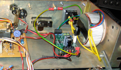
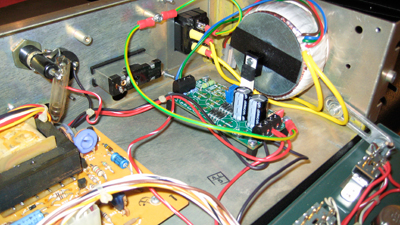
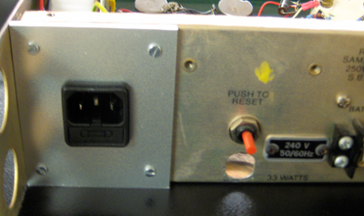
One day I found out that I had a horrible mains hum in my studio when the device was switched off. I had a look at it and noticed that the 'Power' switch does not switch the primary of the power transformer. I decided to get rid of the old power transformer and the stuff around and put in a new power transformer and  PSU (I used a JLM). That did the trick, it' very quiet now.
I will post some photos one day.

I personally wouldn't mod the attack and release times. It does wonderful things with drum signals exactly in the way it's built.
Even if you don't like the sound it's an eye catcher in your rack  ;)
 
hi holger,
wow, thank you so much for uploading the pdf!!  beautiful clean scan! 
so basically you upgraded the entire PSU of the unit?  i'll check how clean the PSU is once i check out the unit.
i'll need to listen to the comp when i get it to see what the person i'm modding it for is talking about.
as i mentioned, it's not my unit and the mod was a request from a friend.  the person whose unit it is has done some major projects so i assume he knows what he wants, but thanks for the insight from your experience (i wanted to ask you your opinion on the need for a mod actually, so you must have read my mind) ;)
thanks again.  it will be a great help to have a clean copy of the schematic when working on the unit.

Holger said:
Even if you don't like the sound it's an eye catcher in your rack  ;)

i know you love the altec look holger.  believe me, i've noticed all your DIY builds with their lovely 'altec', um i mean 'holger' style. ;D
cheers,
grant
 
Grant, I forgot what I've exactly exchanged. I'll look at it over the week end.
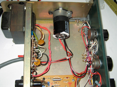
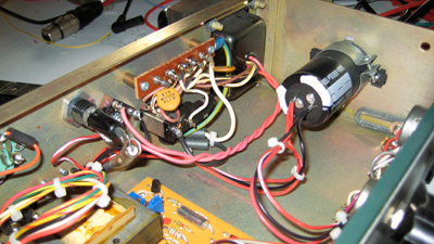
AFAIR I removed the transformer, the circuit breaker, the mains terminal (where you can change the transformers primary from 110 to 220V) and the 4000 µF cap. I 've put in a new toroid and, in one case, a JLM AC/DC which was oversized because you only need one rail, for my second unit I used a SilentArts PosPSU for the 28V.
I left all components on the main board like CR 1-4 because at the time I did the mods I simply wasn't as experienced as I'm now.
And, they surely don't do any harm (I hope...)
I connected the PSU at the 28V battery point. From today's perspective the're more elegant ways.
If you open the device you will quickly find out what I've done.

Unfortunately my 9 month old Ixus camera died. Maybe I'll find a way to make some photos.
 
Original 1612:

1612-before-1.jpg

1612-before-2.jpg


My modification:

1612-after-1.jpg

1612-after-2.jpg

1612-after-3.jpg


-Holger
 
hi holger,
sorry for the late response.  thank you very much for the PSU mod notes and pics.  very much appreciated.
i've read up and there are others who suggest the PSU upgrade/mod so i'm definitely considering doing it (eventhough it's a bit more than i bargained for with this particular project).  you've definitely got me off to a good start with this info.  thank you so much!
kind regards,
grant
 

Latest posts

Back
Top