


babyhead
Well-known member
Hello DIYers-
I recently finished a mic amp based on Forssell's schematic for the 992. As of now, I have the DI wired on a TRS jack with the ring in contact with the tip. The 6.1k termination for the input transformer is before the jack, so there is no termination between the opamp and the DI source.
I then came across this:
http://www.muzique.com/lab/buffers.htm
This is an interesting link/read.
Is this something I should consider to increase performance?
Can I bias to the + dc rail?
I am thinking about a low-none-high switch between the TRS and the opamp. Opinions? Schooling?
Thank you!
:guinness:
I recently finished a mic amp based on Forssell's schematic for the 992. As of now, I have the DI wired on a TRS jack with the ring in contact with the tip. The 6.1k termination for the input transformer is before the jack, so there is no termination between the opamp and the DI source.
I then came across this:
http://www.muzique.com/lab/buffers.htm
This is an interesting link/read.
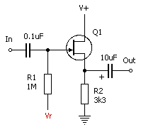
The basic jfet buffer shown in the last paragraph may be improved upon by connecting the gate resistor to a bias voltage instead of to ground. This allows the gate voltage to set the bias at the source to a higher vlaue which increases the headroom and allows a large signal input before clipping. The Vr point on this circuit connects to a bias voltage source as shown in the first paragraph. Input impedance is again approximately the value of R1. It could easily be increased to 10M or more for a cleaner sound with high impedance signal sources such as high-output humbuckers or piezo sensors with only a slight incerase in the thermal noise contributed by the higher value of R1
Is this something I should consider to increase performance?
Can I bias to the + dc rail?
I am thinking about a low-none-high switch between the TRS and the opamp. Opinions? Schooling?
Thank you!
:guinness: