You are using an out of date browser. It may not display this or other websites correctly.
You should upgrade or use an alternative browser.
You should upgrade or use an alternative browser.
JLM Baby Animal
- Thread starter jmiller
- Start date


Help Support GroupDIY Audio Forum:
This site may earn a commission from merchant affiliate
links, including eBay, Amazon, and others.
JLM Audio
Well-known member
All the real 2520's I have have the trim pin cut off so have never added the extra pin hole for it. But yes mounting the 10k resistor on the other side should do it. Just make sure the trim pin doesn't touch the PCB or it may rub through the solder mask to the 0v ground or it could hurt the opamp.One question...what do I do with the Trim pin on a 1731/2520? There is a 10k resistor in the way and I don't want to bend the pin or cut it off. Suggestions? Maybe mount the 10k on the underside of the board?
The OPA2604 is extremely fast and the 99v is fat with silky class A highs. The Hybrid is fast and tight low end with softer silkier top in Class A than the OPA2604 on its own. Don't forget the NE5532A IC opamp as it sits somewhere in the middle of the OPA and 99v.Has anyone heard the Baby Animal A-B'd between an OPA2604 and the JLM99v. I've got 2 99v+JLM14; 1 Hybrid(A/B)+OEP; 1 99v+OEP. I'm putting them in cases tues or wed. The thing is I've been curious if I should look into the OPA2604+OEP as a fifth or if I should add one more of the Hybrid/OEP or 99v/OEP so that I have a second stereo pair? I like having as many options as possible but having a another stereo pair gives me a lot of options too. Any ideas? Help me spend some money.
The 330uF 63v cap only needs to be in the right spot if you are running 62v power rail in to the BA. Have found that some of the 10ohm metal film resistor go open circuit just due to the charge up current of the filter caps. So all new kits have 10ohm carbon which do not do this and if there is a real fault will smoke instead of going open circuit with no external sign. So if you have a 10ohm go open circuit change it for a 10ohm carbon type. If the carbon starts to smoke you have a real fault. If it doesn't smoke all is ok.So here I am thinking I'm all hot sh*t for building 4 BA's and what happens when I plug the first one in? Blow a resistor up. Yup. Me in my newbie haste didn't notice the 330 cap mixed in with the rest of those big caps. I think I placed it in the wrong spot and placed a 470 there and placed the 330 in a 440 spot. So I've now taken the cap out and am out side smoking to calm down. Could this have blown the 10 ohm resistor?
Help please!
The 99v should have more head room than most pre amps so check that the + opamp pin is getting the full +48v or +62v and 0v opamp pin is at half the volts of the + opamp pin. Should be able to put out +26dBM (on 48v rail) and with our JLM111DC wired as 1:2 it can do +32dBM. The only clipping you should hear is the gear plugged into the output of the mic pre being clipped. Also if you are running high line levels into the mic pre don't expect the small JLM14 to take the level without having to turn the 20dB pad on.It seemed to clip sooner than anything
OverSound
Member
Thanks Joe. :grin: :green: :grin:
One more question...
On the Hybrid opamp the 2 square pads between the zeners puts it in A/B mode right? And if that's the case what's the best way to join them? Should I lay a small piece of wire across and solder them? That seems a little wierd to me.
Thanks again
Brad
One more question...
On the Hybrid opamp the 2 square pads between the zeners puts it in A/B mode right? And if that's the case what's the best way to join them? Should I lay a small piece of wire across and solder them? That seems a little wierd to me.
Thanks again
Brad
OverSound
Member
So after one more blown resistor I figured out what happened. Got it working and went to plug the thing in. This is when I realized that I was missing one of my mic cables and couldn't plug a mic into it. I think one of my kids ran off with the cable. Anyways, I decided to plug my bass into the DI instead to listen to it and there is something wrong.
1. First and most notable is that it's distorted. Only when you play at full strength. If you just lightly finger the strings it has little or no audible distortion. I also tried my guitar with the same results.
2. There is a buzz that's audible at medium to hi gain. I tried unplugging the instrument and it stayed. Then I unplugged the pre and it went away. Plugged everything back in and moved around with no noticable change.
I'm really new to this and really worried. What could the problems be? Oh I also ran a chassis ground to 0v after I heard the problem. This didn't help anything.
This pre I set up is the 99v/JLM14 powered by the smps(?) the 48v smaller supply available from JLM.
Any suggestions or help would be greatly appreciated.
Brad
mattmoogus
Well-known member
Hi Brad, first of all dont worry, i doubt its a serious problem.
Firstly, did you try putting the pad in? Some sources can still put out enough level to overload the input transformer (which is after the active DI circuit).
What volts are you getting at the + rail pin of the opamp, and at pin 8 of the 2604 IC on the DI? What volts are at the + input of each opamp? You should see 48v on the + rail and 24v at the + input.
You should take some high res photos (with marco on) of the BA and your wiring and send them to joe. He can often spot the problem from the picture.
M@
OverSound
Member
I'll measure those when I get home from work. I'll take the photo's too. I did try the pad and because of the system I have (M-Audio FW410) I had to plug it into the built in pre amp on the interface. This has a pad too. Tried both of these pads. Don't know if that matters. :?
Thanks Matt
Thanks Matt


![Soldering Iron Kit, 120W LED Digital Advanced Solder Iron Soldering Gun kit, 110V Welding Tools, Smart Temperature Control [356℉-932℉], Extra 5pcs Tips, Auto Sleep, Temp Calibration, Orange](https://m.media-amazon.com/images/I/51sFKu9SdeL._SL500_.jpg)


unheardof
Active member
OverSound, with the FW410, you would probably want to connect your Baby Animal to one of the line inputs on the back instead of the mic/instrument input on the front. If it's like most interfaces of this type, the line input will let you bypass the crappier amplifier circuitry in the 410 mic preamps.
I have the Digi 002R and the first four inputs also have mic pres built in, but 5-8 are just line inputs, so those are the ones I use with the BA.
I have the Digi 002R and the first four inputs also have mic pres built in, but 5-8 are just line inputs, so those are the ones I use with the BA.
OK I have hooked up my BA this evening, and I have obviously made a mistake somewhere.
When I connect a mic, I found that I only get a good signal with the gain pot (roughly) in the centre position. More gain gets me clicking/popping
The DI works, so something is right :grin: but again, it seems that the more gain gives me loud clicking/popping
I'm a newbie at this, so I could do with a few pointers to get me started troubleshooting this. BTW, I am using the small 48V PSU.
TIA
Neil
OverSound
Member
[quote author="mattmoogus"]Firstly, did you try putting the pad in? Some sources can still put out enough level to overload the input transformer (which is after the active DI circuit).
What volts are you getting at the + rail pin of the opamp, and at pin 8 of the 2604 IC on the DI? What volts are at the + input of each opamp? You should see 48v on the + rail and 24v at the + input.
M@[/quote]
So here's what I got Matt...
+in = 24.5v
out = 47.8v
-v = 23.92v
+v = 25.25v
Pin8 = 47.8v
I went through and checked all of my signal path from instrument to cable to crappy FW410 mic pre. All work just fine. So I can safely say that leaves the BA. Though in this process I found that my guitar and bass both have grounding issues that I'll fix at a later date. :grin:
So back to the BA. I re-did all of the power supply and mic i/o's. Checked my 0v connections and did another "visual" check of all parts. I tried it again and found that when I plug any source into the DI it distorts. Still. I have yet to send my pic's to Joe. My camera is lent out at the moment. where does this leave me?
Do those voltages seem odd?
Thanks again for all the help Matt and Joe. It really means a lot to me.
Brad
(edit)
I've now tried 2 different pre's. Both the same 99v/jlm14 combo. And have now run Mic's and Ins. through both and they sound the same. Lot's O' hum and no real gain to speak of. I'll have pic's of the kits up in the morning and also sent to Joe. I'm stumped...
mattmoogus
Well-known member
Hey Brad,
Ok theres def something wrong as the +in and out of the 99V should be sitting at half volts, so 24v. The +rail pin should be at 48 and the - rail pin should be 0v.
First of all take the 99V out, in case it gets damaged while youre trying to fix it. You dont need it in there to make the nessesary measurments, in fact its always a good idea to measure the sockets with the opamp unplugged and make sure theyre all sitting at the right voltage before you ever plug the 99V in. I still do this for every one I build.
Are you sure that you have the PSU wired to the BA the right way around? Measure that 48v is at the + power input of the BA board and the 0v point is actually at 0v.
Have you fitted any of the reg parts?
Well have to wait and see what Joe says when he gets your photos. It might be a good idea to go over all your solder joints and make sure theyre all clean and neat and theres no shorts between pads, as some are very close to eachother.
M@
OverSound
Member
Yeah I checked all the joints. They are all clean. I've measured the voltage of the DC connector of the power supply and matched it up with the pins on the jack. I actually had the polarity reversed on the first one. That's when I blew that 10ohm resistor. I went through and double checked resistor layout and they are all in place. The only thing I'm concerned about are the caps that are under the opamp. I can't read any markings on them and placed them according to all the Pic's I've seem on here and on jlmaudio.com.
hmmm...
I'm feeling really dumb right now.
Brad
hmmm...
I'm feeling really dumb right now.
Brad
Well a little progress for me. I know have messed about with a few things.
1st off I had a dodgy mic cable :shock:, so I replaced that.
I have also had a play with the settings on my sound card (1820M) and things are working quite well :grin:
BUT I still cannot turn the gain up much past half way without the constant popping noise coming up :roll:
Am I simply overloading my soundcard? Or do you think that this is a problem with the BA?
Thanks
Neil
PS if I pull the mic cable from the mic, I get a very loud distortion (sounds a bit like a fog horn). I guess that this isn't normal
1st off I had a dodgy mic cable :shock:, so I replaced that.
I have also had a play with the settings on my sound card (1820M) and things are working quite well :grin:
BUT
I still cannot turn the gain up much past half way without the constant popping noise coming up :roll: Am I simply overloading my soundcard? Or do you think that this is a problem with the BA?
Thanks
Neil
PS if I pull the mic cable from the mic, I get a very loud distortion (sounds a bit like a fog horn). I guess that this isn't normal
OverSound
Member
I've been getting something very like that also....
Here are some pic's...
Let me know what you think.


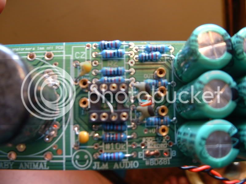 Sorry for the blur. I tried everything to get a closeup of that part of the board without blur but to no avail.
Here are some pic's...
Let me know what you think.
I redid my power & signal cables, and things seem a little better. I can enough gain for my condensor, and it sounds BIG :grin:
Sadly, When I try and turn the gain up higher for the dynamic mics, I still get the clicking. I doesn't seem so bad now, but I cannot get enough gain to make it useable for the SM57 BTW I notice that the clicking seems to come out of the mic, as well as the soundcard!
I have a DI on this build, and that sounds good to me, but also suffers from the problem with the gain pot past the critical point.
I also don't think that this is a case of overloading the soundcard. I put the pad on, and the click starts at the same position of the gain pot.
Anyway, I love to hear some suggestions what to check next.
Sadly, When I try and turn the gain up higher for the dynamic mics, I still get the clicking. I doesn't seem so bad now, but I cannot get enough gain to make it useable for the SM57
BTW I notice that the clicking seems to come out of the mic, as well as the soundcard!I have a DI on this build, and that sounds good to me, but also suffers from the problem with the gain pot past the critical point.
I also don't think that this is a case of overloading the soundcard. I put the pad on, and the click starts at the same position of the gain pot.
Anyway, I love to hear some suggestions what to check next.
Schmilsson
Well-known member
Oversound, haven't you got that 63v cap on the DI the wrong way?
OverSound
Member
Ironically of the 4 I put together that's the only one with that cap reversed. I put that DI in the case after I checked the first 2. I have not tried this DI since the Pic was taken. Thank you for pointing that out before I really F'd up something else.
Schmilsson
Well-known member
I seem to be missing two 220K resistors and a 47pF ceramic cap. No biggie since I'm ordering some other stuff. Would these work as replacements?
http://www.elfa.se/elfa-bin/setpage.pl?http://www.elfa.se/elfa-bin/dyndok.pl?dok=2012484.htm
Don't really know which cap though..
http://www.elfa.se/elfa-bin/setpage.pl?http://www.elfa.se/elfa-bin/dyndok.pl?dok=2012484.htm
Don't really know which cap though..
JLM Audio
Well-known member
I think you mean between the diodes but yes soldering them together reduces the bias voltage from 2v (30mA) with the LED to 1.2v (4mA) with the 2 diodes. Just a small bit of solder will join the two pads no wire needed.On the Hybrid opamp the 2 square pads between the zeners puts it in A/B mode right? And if that's the case what's the best way to join them?
OK voltages below taken with opamp fitted but most voltages will line up with opamp not plugged in.So here's what I got Matt...
+in = 24.5v
out = 47.8v
-v = 23.92v
+v = 25.25v
Pin8 = 47.8v Do those voltages seem odd?
Can you send me a MP3 of the popping noise and any other strange sounds coming from the BA to my normal email so I can see if I get a clue to what is going on.BUT I still cannot turn the gain up much past half way without the constant popping noise coming up
:shock:BTW I notice that the clicking seems to come out of the mic, as well as the soundcard!
Yes they are smaller in size but fine. Basically any 1/4 to 1/2watt 1% metal film of the right value will work. If anyone is missing any parts from our kits feel free to send me a email with your address and missing parts list and we will ship them straight out to you.I seem to be missing two 220K resistors and a 47pF ceramic cap. No biggie since I'm ordering some other stuff. Would these work as replacements?
New BA panels and cases just arrived finally and I will get all the new kit info up on the web site over the next week.

Schmilsson
Well-known member
What about the cap? Don't want to get the wrong one. No need to bother sending any from aus in my case since I'm ordering stuff anyway.
It was a pretty easy, educational and foremost FUN thing to build btw! Nice work Joe! Can't wait to get it hooked up and hearing it in action.
I'm making half rack panel design for a friend to cnc, is there any possibility of getting a blueprint or something of that front panel so I can snatch the exact spacing between toggles and so on? Would be stellar.
bluesgirl
Member
Ok Yes I have the same issue with the 10 ohm resistors going bad. It happened last weekend.
Until I read the post here from Joe I thought I did something really wrong but the only thing I did different was plug in the xlr type plug from the 62v pw supply in the socket when the pw supply was already on. I figured that would be no different than having it on and having a switch on the preamp and turning it on. So I couldn't figure what happened. It took some searching to finally figure out the 10R's were bad.
The 10R's were reading 165k and other preamp's read 125k while on the board. But when I removed them one read 2.2 meg and the other 6.7k respectively. How that is I am confused? :?:
Do the resistors read differently when on the board? Because I am getting weird readings for the 220k's at 9.8k and the RL is reading 470 ohm (I think 470 ohm since I don't have the preamps in front of me), two of the 6.8k's are reading 3.4k, and most of the 10k's are reading correctly but they take a long time to get the correct value. All the rest are reading correctly and get to their values quickly. These readings of course are all being taken with no power to the preamps.
I don't have any way of testing the capacitors.
I used some extra 10k ohm's in place of the 10R just to see if it would work. It helped the one preamp to work, which was extremely distorted before. I also stuck a set of headphones on the output jack of that preamp and it sounds clean. But if I use the headphones on the output jack of the other preamp it is distorted but it sounds ok if it is ran through my soundcard. Nothing is different between the two except the one distorted thru the headphones has the DI on it.
All of this is kinda weird. :?
Everything was working beautifully before this happened.
What if, just to test it, elliminate the 10R's until I get a few of the carbon replacemnts? How much difference would 10 ohms make?
Any help would be appreciated!!
Thx,
Tammy
Similar threads
- Replies
- 1
- Views
- 273