JLM Baby Animal

GroupDIY Audio Forum

Help Support GroupDIY Audio Forum:

This site may earn a commission from merchant affiliate links, including eBay, Amazon, and others.
What are these?

DSC01785.jpg


Also, why do the kits come with 4 jumpers? You only need a maximum of 2 don't you?

Cheers

Nick
 
What are these?

Those are the bezels for the 3mm LED for the phantom power.

It comes with 4 jumpers because you could use up to 4. That is all contingent on what input transformers you are using and if you are using a direct input. For instance, the two jumpers you are probably referring to are used in place of the ribbon cable going to the direct input.

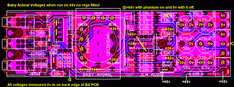
Baby%20Animal%20PCB%20voltages.gif
[/url]

The other two jumpers are used depending on which input transformer you have for that pre. They are labeled on the layout to the right of the "direct in" jumpers in TINY white print. You should see it on the board as well. You have to refer to the chart on the JLM site at
http://www.jlmaudio.com/Baby_Animal_Mic_Pre.htm and look under "Jumper". Either use the jumpers for high, low, or NF (not fitted) which is for the JLM 1:4 transformer.

Adam
:sam:
 
Got those values in place. Now, how can I find out which wires on this Tamura are primary and which are secondary?

Transformer Red and Brown are primary so they will go to where the BA overlay has Green and Red marked but cannot remember which is hot or cold for polarity so you will have to try it against another BA to see.

Transformer Green and Black go to where blue is marked on the BA overlay and Transformer Blue goes to where yellow is marked on the overlay.
 
Well, after a couple of snafu's whilst racking up, I'm up and running :) Like Mr Jones a number of pages back in this thread, my previous experience is with low level pre's, and this little beast has indeed been pants-blowing!!

I've got a couple of things to sort out, including that my DI is perilously close to parts of the case and liable to short if I don't get it right.

I do have one issue that has me scratching my head - from time to time I get an intermittent buzzing sound whilst running a condensor mic with the phantom power on. It appears out of nowhere and then disappears again. It was worse at a mate's place, and I suspect it may be a sensitivity to the quality of the mains. Not sure - can anyone assist here? Note I smoked 2 of the 10R's before getting it right, and blew up the 330 uF cap, each of which are in the path for the phantom power, so all of this (or none of this) may be interrelated.

Any thoughts?

Otherwise, Joe - top stuff man :green: :green: :green: :green:
 
Looks like I've sorted it out - all is good :green:

A couple of pics (I can only afford to do one channel at a time!)

Baby_Animal_Case.jpg


Baby_Animal_Guts.jpg


Baby_Animal_One_Channel.jpg


It just entered the "best gear in my studio" charts at #1...lovin' it! :thumb:

Somewhere down the track I'll label the front panel, and get some black knobs to replace the silver ones I currently have.

The only concern is that the DI is close to touching the transformer - as long as they stay in place there's no problem, but as we all know things tend to move over time. I'm thinking a piece of duct tape on the top of the transformer would prevent any shorts?

Cheers guys
 
Nice job Astrovic! I have 8 Baby Animals in two racks. As you add to the rack, I would suggest using different opamps and transformers to give each one a little different character. It really does nicely when mixing down tracks. I have 4 different pairs:

2 with 99v and JLM transfo
2 with JLM Hybrid and JLM transfo
2 with Fabio 2.5.2.0 and JLM transfo
and 2 with 99v and Tamura tranfo (from Yamaha PM2000 channel)

I did a similar thing with the front panel where I ordered a panel from JLM and then used it as a template for the other, which is plain black with no labeling.

JLM is the shiznit, yo!

Adam
:sam:
 
Two questions:

I just soldered my beyer 1:10 transformers to the Ba pcbs, and realised i didnt isolate the transformer from the pcb.

Then i realised that however i tried to isolate them from the pcb, the center hole in which you mount them is connected to ground. So theres really no way to insulate the transformer shield from ground.

I also measured across the tracks which the transformer case and bolt covers a bit, and there was no shorts.

So i should be ok, right?

I mean, it cant hurt to have the transformer shield connected to ground right? (I also have the ground wire from the transformer connected to ground btw)
Or am i missing something here?

Question two:

I measured with my dmm across the transformer secondaries and all of my beyers except one measured about 4.6-4.7k ohm. The last one measured about 5.4k instead. Should i be worried that something might be wrong here?

Thanks!
/jonas
 
Thanks J - it'll look better when the whole unit is filled.

Barney put me on to those knobs - if you go back a couple of pages, you'll see he used the same ones. I think they look better against a black panel myself - I was originally going with a metallic blue panel, and bought the silver knobs, then realised that the lettering (whe I do it) won't show up very well. So I switched to silver, and silver on silver is a little...not quite right. But it still sounds great :green:
 
I'll be ordering a couple more channels this week. I'll probably give the JLM99V opamp a try.

I have a couple of OEP A262A2E transformers lying around getting bored. I understand I can use these in the BAs but on the xformer chart RL, CL ,RZ etc values are only given for the OEP262A3C. Can I get a bit of help with these values?

Data sheet is here:

http://www.canford.co.uk/commerce/resources/catdetails/2739.pdf

What sort of max. gain can I expect using these?

Cheers

Nick
 
Nick,

Try running it at 1:4 - that'll give you 61db as per the table.

You can then try copying the values for the JLM14 which will probably be fine.

Perhaps Joe will chip in.
 
[quote author="rodabod"]Nick,

Try running it at 1:4 - that'll give you 61db as per the table.

You can then try copying the values for the JLM14 which will probably be fine.

Perhaps Joe will chip in.[/quote]That makes sense, thanks. :thumb:

Cheers

Nick
 
Well, after a couple of snafu's whilst racking up, I'm up and running :) Like Mr Jones a number of pages back in this thread, my previous experience is with low level pre's, and this little beast has indeed been pants-blowing!!
:grin:

I do have one issue that has me scratching my head - from time to time I get an intermittent buzzing sound whilst running a condensor mic with the phantom power on. It appears out of nowhere and then disappears again. It was worse at a mate's place, and I suspect it may be a sensitivity to the quality of the mains. Not sure - can anyone assist here? Note I smoked 2 of the 10R's before getting it right, and blew up the 330 uF cap, each of which are in the path for the phantom power, so all of this (or none of this) may be interrelated.
Check all the case panels buzz together and if they don't use a drill bit to take of some paint in the countersink holes for the screw heads. Make sure the 0v for the DC connector is connected to the case by its nut ok.

just soldered my Beyer 1:10 transformers to the Ba pcbs, and realised i didnt isolate the transformer from the pcb.

Then i realised that however i tried to isolate them from the pcb, the center hole in which you mount them is connected to ground. So theres really no way to insulate the transformer shield from ground.

I also measured across the tracks which the transformer case and bolt covers a bit, and there was no shorts.

So i should be ok, right?
The bolt on transformer doesn't need to be isolated from the PCB if it doesn't short any pads or cut into any tracks running under the nut etc.

If there are no shorts should be fine but if you are not sure use a small square of electrical insulating tape or a fibre washer.

I measured with my dmm across the transformer secondaries and all of my beyers except one measured about 4.6-4.7k ohm. The last one measured about 5.4k instead. Should i be worried that something might be wrong here?
Do they seem to be from the same batch and are they definitely the same long Beyer id code?

I have a couple of OEP A262A2E transformers lying around getting bored. I understand I can use these in the BAs but on the xformer chart RL, CL ,RZ etc values are only given for the OEP262A3C. Can I get a bit of help with these values?
We don't use the OEP A262A2E because it rings badly. But since you have some and I have one here somewhere I will try it in the baby Animal and see if I can load and zobel it in 1:4 ratio and get it to work.

From my Neve transformer info web page

The OEP A262A2E which is sold by RS as part no. 210-6419 with screen can 210-6469. And by Farnell part no. 149-155 with screen can 149-157. The transformer was wired as 1:2 with both sets of winding in series. Giving 600:2k4ohms. The idea being that the 6k load on the 2k4ohm side would reflect over 1200 on the 600ohm side just like the 10468 is right and can be done with many transformers but not this one. The ringing was so big I could not fit it on the screen without making all the other graphs to small to easily see. Tried different loading but nothing could control it. This transformer needed a low resistance like 2400ohm across the secondary plus Zobel to fix it which puts it out of the Neve substitute list.
 
They beyers are marked exactly the same. Thats why i am a bit worried.

btw,
I absolutely hate the connection wires on those beyer transformers, especially when compared to the jlm ones. The jlms are thick and nice, the beyers tiny and fragile like crazy.

The beyers break off very easily, and on one of my channels i almost couldnt connect the damn thing because it broke.

/J
 

Latest posts

Back
Top