JLM Baby Animal

GroupDIY Audio Forum

Help Support GroupDIY Audio Forum:

This site may earn a commission from merchant affiliate links, including eBay, Amazon, and others.
I've never used the JLM1:1:1, but from all descriptions it is no transparent Lundahl-type transformer. It has a sonic signature that should be noticeable.

BTW - I really like my BA with JLM1:4 input and hybrid opamp for bass amp and drums. My BAD with Lundahl 1538 inny and 2 FETBlokes and impedance balanced output is the absolute opposite end of the sonic spectrum, and I like it on everything else. Sometime I'll throw a FETBloke in with the JLM1:4 and do a real comparison.
 
I actually found the difference between the JLM 1.1.1 with and without to be very slight indeed. The real difference was the increase of 6db but in terms of sound I didn't notice huge sonic signatures one way or the other. In my mind the difference could be summarised as this - if you really consciously listen you will eventually hear a difference, but when using one or the other for long periods of time and without looking at which config you are using, I bet you can't tell which it is!!

Just my view - please no flame:)
 
any issues anticipated with using a JT-112lpc (jensen).  its 50% steel quadfilar 1:2 (150:600).  it would double the output (similar to api) but be at 600ohms on the output side.

thanks
 
Howdy folks, in celebration of April Fools day here's a fool's story:

Built a BA (JLM 1:4, 99v) and it worked fine right away.  It had a intermittent problem that I found, an unsoldered pad.  During diagnosing this I believe I accidentally shorted the 99v output to -V with a multimeter probe.  This smoked the 10R, and probably the 99v.  Replaced the 10R, and with 99v unplugged the volts read OK.  With the 99v in:

+in = 19v
-in = 9v
out = .2v
-V = 0
Gnd = 19v
+V = 48

With 99v out all opamp sockets have resistances to ground well above 1k.  With 99v in, Out to -V resistance is 28ohms.  Please confirm my foolishness and incompetence, I torched my 99v with no hope other than replacement, correct?

Thanks all.
JMW
 
mr_bungus said:
I torched my 99v with no hope other than replacement, correct?

Yeah, something in the little black box went !POP!.

The amp shouldn't ever be loading down the half-rail bias, (read at GND and +IN), which should always be +24V. You read +19V. Uh-oh.

What's really curious to me is the difference in your readings between OUT and -IN. Those should always ride atop the same half-rail bias of +24V. That bias is fed to the +IN from the junction of the two 10K resistors shunting the full rail voltage, forming a voltage divider and giving us the half-rail, which then shows up at the output and is fed to the -IN across the 10K feedback resistor. Since the -IN doesn't sink any current, there's no voltage drop across Rfb. The result is +24V at both + and - IN and at OUT.

Without seeing the circuit of the 99V, I can't hazard a guess at why the -IN would ever go positive of the output. Since the opamp is isolated from ground at DC by the output capacitor and the capacitor between Rfb and RGain, the only place the output can be pulled that near to -V (0V in this case) is inside the opamp.
 
reminds me of my 2520s that i waited a million years for (thanks to BR for help getting them!!)  only to put them into my 24v BA and fried them.  they are running 2x 990 and 2x 99v now and are happy and healthy!!
 
I have the baby animal set up with vtx-102-003 input /-hybrid op amp /- 1:1:1 output running off the smps 48v supply

I get normal voltages without the hybrid connected but with it in I get no sound. What I do get is a double thump/ click every two seconds and if the phantom power is engaged it lights up in time with it. Measuring voltage now gives a swing from 0 up to 48v at the input from the power supply, that cycles in time with these thumps.

So that’s the problem but bellow is a list of a trillion questions I’ve had while building it. Please bear with me

Do you fit a jumper across hybrid op amp pins (4-7) for the baby animal with the jlm 1:1:1 output tran?

Do I fit the jumper for low/ high ratio selection with the vtx-102-003 transformer?

Vtx-102-003 input transformer do I solder all seven pins to the board? This connects both primaries and same for the secondaries. Or do we just want one primary and one secondary? I’m after 1; 1.65 operation.

My impedance pot has 6 prongs. How to wire?

Does the +v pin for the op amp, which comes from the baby, have to be soldered to the collector of bd139 via the pad on the back of the transistor? Reason I ask is that pin doesn’t seem to have any tracks leading off it that I can see.

Joe said on page 25;
‘WHEN USING HYBRID WITH BA PCB, LEAVE OFF the 47uF cap which is on the opposite side of the PCB to the LED. As this can override the power supply filtering and let noise into the pre.’

This is the one below the bd139 right? Or the one below the bd140, which has an asterisk beside it. There are no 47uF caps on the hybrid schematic?? This is confusing.

Ok that’s all (for now) ha

Scott


Without the op amp fitted i am reading 0v at:

the neg input for the op amp on the ba board,

the 470uF cap for rgain

the 470uF cap between + out of the op amp and the + out to xlr

This is all normal with the op amp not fitted? or should be 24v like on the overlay?
 
Hi !

Tomorrow i will order some BA pcb-s, as i found these can be a nice way to get great results as a diy mic pre.
But i have a question... ( I think later i ll have more :)) )

What do you think about using opa2107 instead of opa2604 ? Will they work ? Will they be better ?
(As i see, i ll have to do that zener+transistor regulation to get the proper 36v(+-18v) supply for them, so that is not a problem.)
I m curious, if they can provide better results sonically, or not ? Do they need any modifications in the passive component values ? (As i see not, but im unsure of it.)


Thanks for the replies, and sorry for my english. :)
 
Hi

As dirk666, I also got this problem with the psu turning on and off. My setup is 4 BA wired to the same 48V psu from jlm, and with OEP and hybrid. This is only a problem when all the BA is connected together with the hybrid installed. Without the hybrid, just the opa2604 installed,  the psu can run all my 4 BAs. With hybrid I can connect 3 BAs.
Another thing is that with the hybrid installed the 48V, drops to 47,2. The 48V is ok with the just the opa.
The 470uf at the 139 is not installed, with class A.

So in my head Im thinking that the 48V psu to small to supply 4 BAs with the OEP/hybrid, OR, I have done something wrong.

Anyway, the pres sounds fantastic with just the opa.

Thanks
 
Howdy - so I have read all of this thread but am slighly confused with some component values for a BA setup to render it sonically similar to an API312. I am using:

Input: Cinemag CMMI -8pca Input Transformer

DOA: An original API 2520

Ouput: Ed Anderson 2503 Output Transformer


So can anyone help me confirm:

1) CL = 440pf
2) CZ = 220pf
3) RZ = 5k1 or 10k cant quite work out with one.
4) RL = 15k and 100k log pot
5) The two 47pf ceramic caps should be replaced with 220pf caps

Am I right????

Any confirmation would be really appreciated

 
deuce42 said:
Input: Cinemag CMMI -8pca Input Transformer

So can anyone help me confirm:

1) CL = 440pf
2) CZ = 220pf
3) RZ = 5k1 or 10k cant quite work out with one.
4) RL = 15k and 100k log pot
5) The two 47pf ceramic caps should be replaced with 220pf caps

4) To do this JLM-style, and to provide a load impedance of ~600R to 3.7K, try an RL of 38K plus a 200K pot. I think your selection would also work ok.

1),2),3) If you copy Cinemag's Zoebel network shown on their datasheet, you can omit CL, and then fit a 10K RZ plus 22pF CZ.

5) Yes, if you want to mimic the original 312's top-end roll-off characteristic.
 
Ok my last BA channel and I have a problem with the DI not working.

Can anyone tell me what voltages I should be getting from Pin 1 on DI board's ribbon connector? I seem to be getting 24v which tells me there is a problem. I am quite certain the DI board works fine though because I cant find any cold solder joints, solder bridges, wrong components, or wrong way mounted diodes  I think the problem is somewhere on the BA board, however the BA board without DI passes good quality signal.

Can anyone point me as to what I am missing?
 
Hello guys....

I am new to the forum and new to DIY...

This is my first project
and so it is a bit fluffy...

Anyway, I know nothing almost nothing about electronic circuits and english is not my first language so I dont go well with terms.

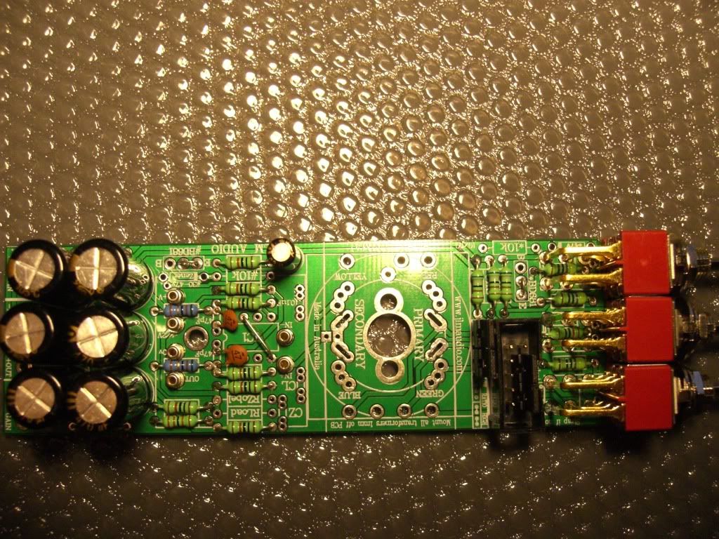
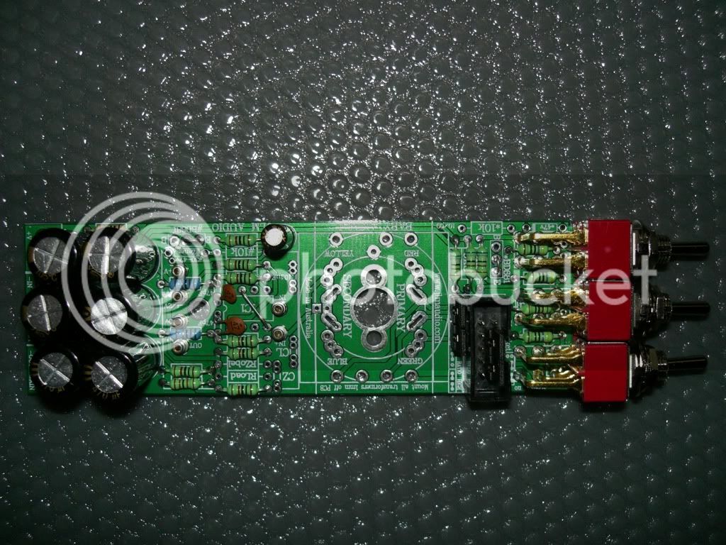
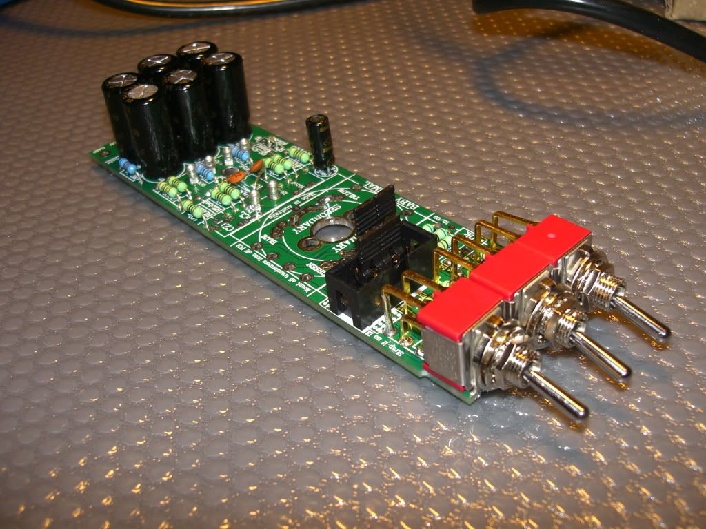
I have managed to go through the scematics and some posts here and came up with what you see in the photos...

Its for a BA PCB with JLM 99v opamp and OEP input transformer. Will be using 48v power supply
To be honest I've only been through the 12 first pages and not all 50...

Now... I need to:
- get my XLR input and output...
- get some wires to connect pot
- solder my OEP
- attach the green things for the xlr's on the back
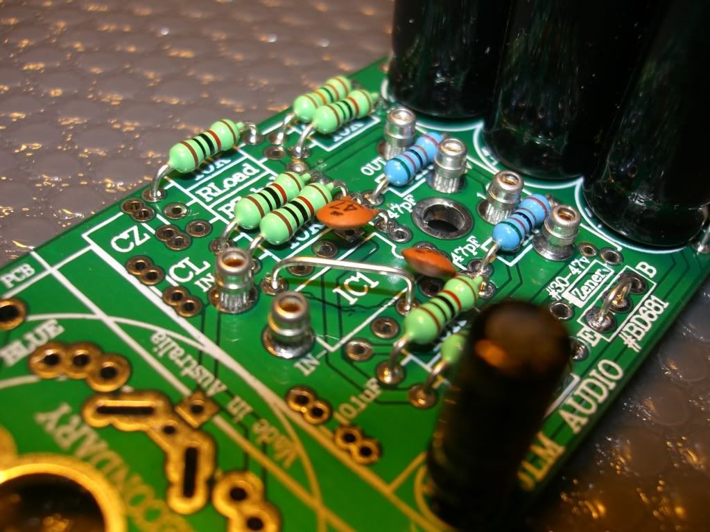
- add 0.1 uF and CL
- get my power supply

What I dont know is:
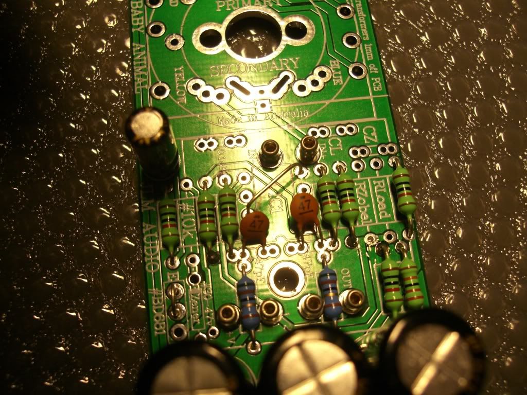
- where do the red/green/blue/yello cables under OEP go....Seems that they will be going to power supply....will I have any switch or just the one from power supply
- The CL and 0.1 uF...? do i connect them in the inner holes or the outer? (all photos I've seen are the older PCB's with just one pair of holes)
- Where does the LED go to? (Is it to show the phantom power is on or not? where does it get attached?)
- I am left with a circular plasitc small bit (size of led light)... where does it go?


I know:
- Left and center pin of pot wired together and then to ''0v''
- Right pin to ''gain'' (these looking pot from back with pins up)
- shield of xlr's to ''0v''
- also ''0v'' going to case
- Pin 2 of xlr in to in+ and pin 3 to in- (respectively with xlr out)

Here is my Baby Animal:
CIMG0007.jpg

CIMG0008.jpg

CIMG0009.jpg

CIMG0010.jpg

CIMG0006.jpg


I am sorry for the long post but I feel very anxious about the whole thing.
Please if possible comment on my words/pcb images
and if possible correct me to anything I've done wrong....


Big Ups to Joe for the great kit and his great help through e-mails
Also big ups for this thread and all the help you guys provide to us newbies.
I really look forward to chatting to lot of you and becoming a member of your community.


Regards
Jim
 

Latest posts

Back
Top