You are using an out of date browser. It may not display this or other websites correctly.
You should upgrade or use an alternative browser.
You should upgrade or use an alternative browser.
JLM Baby Animal
- Thread starter jmiller
- Start date


Help Support GroupDIY Audio Forum:
This site may earn a commission from merchant affiliate
links, including eBay, Amazon, and others.
Dazazone
Well-known member
Nice one ddt!!
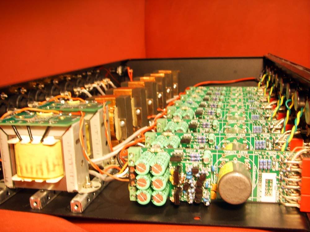
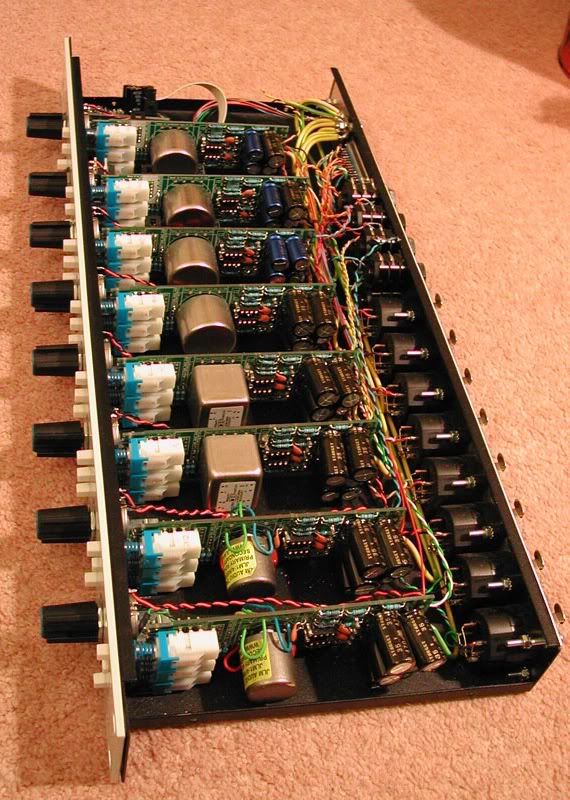
My BA8 has JLM 1:4 input transfos, Gar2520 opamps and 2 channels have Joe's output Transfos, the other 6 are 2503 API copies from Jeff.
I also have 2 BA2s. One with 2 x 1:4 99v 1:1:1, the other is 2 x OEP 99v 1:1:1.
My Favourite combo for most things is the 1:4 99v 1:1:1 combo. It is much more full sounding. The Gar2520 with the 2503 OT is also very cool. It tends to be a little more conservative down the bottom whilst crunching up the middle a bit. Don't get me wrong, the bottom is still there, I think this sound is easier to slot into a mix.
Anyway it was a fun build, I'm lucky enough to live down the road from JLM. Thanks again Joe. Cheers
Are there any more BA8s Getting about?
 azazone:
Dazazone
Well-known member
Thanks Wolfgang
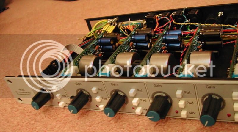
The front panel is my own design, hopefully JLM do a BA8 soon with the kit packs. I'm sure it would be very popular.
I didn't want to have heaps of screws on the bottom so I put the OTs on the rails, 3 screws either side. A bit neater i reckon.
Cheers
The front panel is my own design, hopefully JLM do a BA8 soon with the kit packs. I'm sure it would be very popular.
I didn't want to have heaps of screws on the bottom so I put the OTs on the rails, 3 screws either side. A bit neater i reckon.
Cheers
mac
Well-known member
hey Dan, nice work to squeeze them in,,,
Dazazone, nice build too mate...
Ive only got 4 at the moment - you guys are making me want more!
Did you have to drop the V in on the 2520's? if so, do you run the whole board at lower V?
Mac..
Dazazone, nice build too mate...
Ive only got 4 at the moment - you guys are making me want more!
Did you have to drop the V in on the 2520's? if so, do you run the whole board at lower V?
Mac..
Dazazone
Well-known member
mac said:Did you have to drop the V in on the 2520's? if so, do you run the whole board at lower V?
Yeah I had to wack in the extra 10k resistor, BD681 and 33v zener diode for each board. The rest of the boards run on 48v just the opamps are now getting +/-15 - 16v instead of the 24v which the JLM99v runs on. The Gar2520 is able to run on up to +/-20v. So you could use a 36v or 39v zener to beef up the output and headroom a bit. Apparently it get pretty hot up there but I find there is plenty of output using the 33v. It easlily peaks PTHD straight in and this unit will be mostly used for loud drums.
Cheers


pietro_moog
Well-known member
hi guys.
i built my BAs with stock red diodes. i can barely see them on.
i had yellow ones before, but i wanted to change.
do you think that ultra bright leds could be too much bright?
i tried blue ultra bright leds and normal blue ones, and they are both too bright.
maybe it's a color thing... i don't know..
what do you think guys?
Hey guys, i finished by BA JLM 1:4 and JLM 99v with DI. having a little trouble, DI works fine (1/4" input is fine, pad is fine, output is fine) but i get no output when using the mic input and a microphone. I ordered all parts from joe. BA kit, fet DI kit, power switch kit, DC kit, and I/O kit. i have everything wired the way it is in the pdf diagrams. Also, the gain pot is really scratchy.
0v from DC to power switch to 0v BA PCB
48v from DC to power switch to +V BA PCB,
0v from BA PCB to 0v OUT and 0v IN on the I/O PCB
+In from I/O PCB to +In on BA PCB
-In from I/O PCB to -In on BA PCB
+Out from I/O PCB to +Out on BA PCB
-Out from I/O PCB to -Out on BA PCB
Gain Pot 0v strapped properly and going to 0v on BA PCB
last prong going to GAIN on BA PCB
Im using fixed impedance with JLM 1:4 and JLM99v so..
RL = 10k
CL = 220pf
RPAD = 120R
RG = 68R
RZ = NF
CZ = NF
pins 4 and 7 are strapped on DIP socket
wire strap on both BD681 emitters
im using a DI (which does work) and have the ribbon cable running from BA PCB -> DI -> I/O PCB
ill continue to fiddle, but any help is greatly appreciated
Thanks so much.
mac
Well-known member
Did you use Joes grey flat ribbon cable to connect to the input XLR's or did you wire them yourself?
If it is the flat ribbon, just check the cable for a good connection - use a multimeter to test continuity. I had one of mine which was not making a good connection (black crimp connector on the flat cable)- ended up using balanced cable and hard wiring mine that way instead.
Mac
If it is the flat ribbon, just check the cable for a good connection - use a multimeter to test continuity. I had one of mine which was not making a good connection (black crimp connector on the flat cable)- ended up using balanced cable and hard wiring mine that way instead.
Mac
yes, i used the one that came from Joe already crimped. I just unplugged the DI and ribbon (and then put the two jumpers where there ribbon cable was) and the mic input works! im so confused on how i can get DI to work and the MIC IN to work, but with the same means of wiring. hopefully somebody can point me in the right direction.
after speaking with Joe, we determined the diode on the DI was on the wrong way. oops. its up and running now. just waiting for the paint to dry on the front panel. i have a fpd file ready to send off when the funds allow for it.
pietro_moog
Well-known member
hi guys.
i noticed that my BA's are really noisy, with big hum!
not a big problem, just an hi noise-floor.
i built mines with the DC power supply.
why? is toroid and power supply a better solution?
i noticed that my BA's are really noisy, with big hum!
not a big problem, just an hi noise-floor.
i built mines with the DC power supply.
why? is toroid and power supply a better solution?
pietro_moog said:hi guys.
i noticed that my BA's are really noisy, with big hum!
not a big problem, just an hi noise-floor.
i built mines with the DC power supply.
why? is toroid and power supply a better solution?
Hum? Or white noise?
Possibly an earthing issue.
mcfarlane_audio
Well-known member
Alright, in the process of buttoning up a BA4 and have run into some issues.
have started troubleshooting but would appreciate some help.
I have them all assembled but no op amps in as of yet.
-there are 2 connected to di's (#1,2)and 2 not.
-all running off of a small psu
Voltages are as follows
1.
in + = 24
in - = 0
out = 24
0v = 0
1/2v= 24
v+ = 48
blue and yellow wire = 24
this all seems correct except for the in- the overlay shows this as =24??
2. -same as 1
3.
in + = 0
in - = 0
out = 0
0v = 0
1/2v= 2
v+ = 48
4.
in + = 0
in - = 0
out = 0
0v = 0
1/2v= 0
v+ = 48
seems like i have a jumper / connection wrong?? all the phantom points and connections work perfect.
im a bit confused so any help would be amazingly appreciated.
are you using hybrid opamp ?i noticed that my BA's are really noisy, with big hum!
Out of the Blue
Well-known member
Hey dazazone,
nice build! How did you do the variable impedance?
nice build! How did you do the variable impedance?
pietro_moog
Well-known member
hi guys.
i don't remember precisely the kind of noise. i just remember i heard it.
i have 99v + jlm14.
one channel more than the other. i had a dynamic mic plugged in and 3/4 gain.
with silence i heard the noise on the back ground, very quite but present. one more than the other.
the circuits are properly built. electrical noise, maybe white noise + buzz.
i took the DC plug off and the noise went away (the preamp still have power for a few seconds)
may be it's a ground related problem, but the ground is so easy on this: i have 0v on the DC socket, that goes to
0v on the 2 BA (in series) and those are connected to pin 1 on the XLRs. i'll check but it seems to me that connections are pretty good.
any experience with such a noise?
Dazazone
Well-known member
Out of the Blue said:Hey dazazone,
nice build! How did you do the variable impedance?
Hi Out Of The Blue
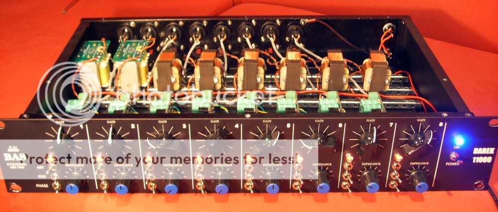
The variable impedance for my BA8 is just a 50k Alpha log pot hooked up to the RL with a 2k2 resistor in series. These parts came in my first 2 BA2 kits before Joe changed to the little green centre detent dual 100k pots. 600 ohms is around 10 o'clock with this input tx setup but I like to use them for tone tweeking so each instrument slightly varies on its position and also depends on mic choice of course.
The 50k pot 2k2 resistor and the other usual bits on JLM baby animal web page tables (link RZ and add 220pf to CZ). Nothing out of the ordinary.
I've been using the BA8 in a few recording sessions now and it is insanely awesome! GSSL next 8)
Out of the Blue
Well-known member
Thanks man. I BET it sounds awesome!
buschfsu
Well-known member
guys i have a BA4 - 2 ch oep/2520 and 2 ch jlm1:4/jlm99v...
question is has anyone compared the 1:1 output vs the impedance balanced scheme on the board? as its 1:1 im wondering if there will be much audible difference?
thanks
question is has anyone compared the 1:1 output vs the impedance balanced scheme on the board? as its 1:1 im wondering if there will be much audible difference?
thanks
Similar threads
- Replies
- 1
- Views
- 271