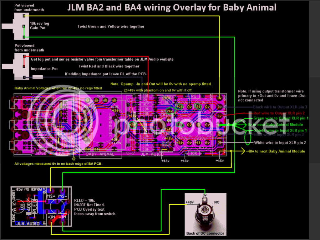
What I dont know is:
- where do the red/green/blue/yello cables under OEP go....Seems that they will be going to power supply....will I have any switch or just the one from power supply
The spots with colour markings are for the JLM Input TX which has leads instead of PC-Pins.
So just put the OEP in where it fits and solder it ! Forget the colour holes - you dont need it!
solder them where the cap fits better! they are connectet together!- The CL and 0.1 uF...? do i connect them in the inner holes or the outer? (all photos I've seen are the older PCB's with just one pair of holes)
- Where does the LED go to? (Is it to show the phantom power is on or not? where does it get attached?)
You have to solder the LED directly to the 48V Switch! I dont know the right legs out of memory but i am sure you will find he information oon the JLM-site!
- I am left with a circular plasitc small bit (size of led light)... where does it go?
This is for the JLM Input TX! you have to screw it and this small washer is to keep distance between the TX and PCB. So to NOT have any short!
I hope this helps!
enjoy the preamps!! they are great!!
regards,
Wolfgang


![Electronics Soldering Iron Kit, [Upgraded] Soldering Iron 110V 90W LCD Digital Portable Soldering Kit 180-480℃(356-896℉), Welding Tool with ON/OFF Switch, Auto-sleep, Thermostatic Design](https://m.media-amazon.com/images/I/41gRDnlyfJS._SL500_.jpg)


