JLM Baby Animal

GroupDIY Audio Forum

Help Support GroupDIY Audio Forum:

This site may earn a commission from merchant affiliate links, including eBay, Amazon, and others.
Hi!

I've just ordered a Baby Animal kit and am really excited to put it all together. Because my eager to get started I thougt I could do a stepped resistorswitch meanwhile.

In the BA circuit scheme, it sais 10k reversed log pot (or switch with stepped resistors). The only place I can find suggestions for resistor values in such a switch is on the JLM page, but those values are for Dual 99v. They go as far as 120k at the highest and also there is a different value on the resistor in series with the stepped resistors. So in other words I dont't think I can use those values for the BA, am I right?

It would be really nice to get a suggestion of resistor values that will do 5dB steps in gain, from the maximum and downwards. I really hope I haven't missed this question in the thread or elsewhere. (By the way, I will use Lundahl 1578XL in 1:5, a JLM99v op and no output op. Will probably end up at 59dB maximum gain)

Many thanks,
Jon
 
Hey Jon,
did you try searching the JLM support forum for this info? You probably already found it but just in case http://www.jlmaudio.com/phpbb3/

I only stumbled upon it after I had just completed recently building four channels of baby animals!! ;D

Otherwise I am sure MattM or Joe will respond with the required info.

Cheers,
Mac.
 
jonte-72 said:
In the BA circuit scheme, it sais 10k reversed log pot (or switch with stepped resistors). The only place I can find suggestions for resistor values in such a switch is on the JLM page, but those values are for Dual 99v. They go as far as 120k at the highest and also there is a different value on the resistor in series with the stepped resistors. So in other words I dont't think I can use those values for the BA, am I right?

It would be really nice to get a suggestion of resistor values that will do 5dB steps in gain, from the maximum and downwards

Hi Jon,

I think it might be nice to make this a simple exercise in basic opamps.

Have a look at the schematic; with the input going into the non-inverting input, and a feedback loop from the output to the inverting input, we can see it looks roughly like an opamp configured for non-inverting amplifier operation.

Following the basic plan for this type of amp arrangement, what is often described as Rf is the 10K feedback resistor, and Ri would then be our 10K gain pot (or stepped ladder of resistors) which provides a variable resistance. Let's ignore the 68R resistor Rg and the 220K on the BA schematic.

The gain for this generic amp is defined by (Rf/Ri)+1. Rg is there to stop gain going through the roof as our gain pot approaches zero Ohms and caps it at gain = (10K/68)+1 = 148 which in terms of dB equals 20*log 148 = 43dB. We kind-of don't need to be too concerned with the 220K resistor; it makes the gain not quite reach unity, but by a negligible amount as far as we're concerned.

So, as far as gain is concerned, decide first of all what your min and max gains are going to be. This depends on your transformer choice, and their ratios. Then, add the transformer gain to ~0dB for minimum gain, and 43dB for maximum gain. Now decide what steps you'd like in between this range.

Now to consider how to find the required value of Ri for a given gain; work backwards after figuring out the actual gain formula.

Gain (as a multiplier, not expressed as dBs) when taking Rg into consideration too is ~ (10K/(Rg+Ri))+1

Gain-1 = 10K/(Rg+Ri)
(Gain-1)/10K = 1/(Rg+Ri)
10K/(Gain-1) = Rg+Ri
Ri = (10K/(Gain-1))-Rg

So, for example, for 30dB of opamp gain (that's a gain of ~31), I reckon we'd want Ri = (10000/(31-1))-68 = 265 Ohms

To test, I'll plug it back into the gain formula of Gain = (10K/(Rg+Ri))+1 ...... = (10000/(68+265))+1 = 31

Convert gain of X31 to dB, we get 20*log 31 = 30dB

So, I reckon you could probably chuck that Ri formula into a spreadsheet to make some values, or you could plan them on paper for each step.

I hope that maybe helps in some way if you fancy doing this yourself.

Cheers,

Roddy
 
Roddy - this was really informative and useful for me. Even though I just used supplied reverse log pot for my own build, this formula made sense and clarified a lot to me.

Nice one!
 
Wow!

That was really informative and fun to read, Roddy!    Now I really have some fun maths to do in the summer :)  Thx a lot!

mac said:
Hey Jon,
did you try searching the JLM support forum for this info? You probably already found it but just in case http://www.jlmaudio.com/phpbb3/
Also to mac: thx for the tip. I had visited one of the threads at JLM, but I had missed the tons of other threads that existed there. Really helpful!  :)

Cheers!
/Jon
 
Hi!

I got a question some time ago on what values I got when I calculated the resistor values. So I thought I could post it here in case someone else could have use for it. Of course, I cannot totally guarantee that I haven't made an error. In a week or two I will have my BA finished, and then I will write here again to confirm that everything worked out.
My values were initially based on 3 dB steps. Then I decided to go with a 24 stepped rotary switch. So I added 1.5 dB steps in between. Since I have no output transformer I have only 59dB maximum gain, I found it more valuable to have smaller steps. However, with this setup, it's not possible to reach unity gain (0 dB gain). Not that I personally have use for that, but just so you know. All calculations have taken the 68R resistor (that lies in series) into account. When using the available resistor value the error will give approximately +- 0.1 dB at most. This error could be smaller if using combination of resistors. Then another +-0.1 dB will be the result of the accuracy in the resistors (based on +- 1%). For me this is not the important thing. The important thing is once you have recorded something and want to to more takes at a later stage you will get the exact same gain time after time. Also, a quality switch will work reliably for a long time.

The values:
(gain in relation to maximum gain; calculated R value; closest available resistor value)

0 dB; 0; 0 R
-1.5 dB; 12.92; 13 R
-3 dB; 28.32; 28 R
-4.5 dB; 46.69; 46.4 R
-6 dB; 68.60; 68.1 R
-7.5 dB; 94.77; 95.3 R
-9 dB; 126.05; 127 R
-10.5 dB; 163.47; 162 R
-12 dB; 208.31; 210 R
-13.5 dB; 262.12; 261 R
-15 dB; 326.80; 324 R
-16.5 dB; 404.74; 402 R
-18 dB; 498.91; 499 R
-19.5; 613.05; 619 R
-21 dB; 751.96; 750 R
-22.5 dB; 921.82; 931 R
-24 dB; 1130.8; 1130 R
-25.5 dB; 1389.7; 1400 R
-27 dB; 1713.4; 1690 R
-28.5 dB; 2122.8; 2100 R
-30 dB; 2647.9; 2670 R
-31.5 dB; 3334.0; 3320 R
-33 dB; 4252.4; 4220 R
-34.5 dB; 5522.0; 5490 R

Of course the padswitch on top of this will attenuate more dB.

So that's my homework. Cheers!
/Jon
 
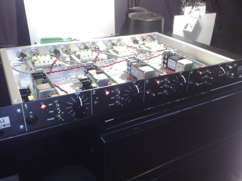
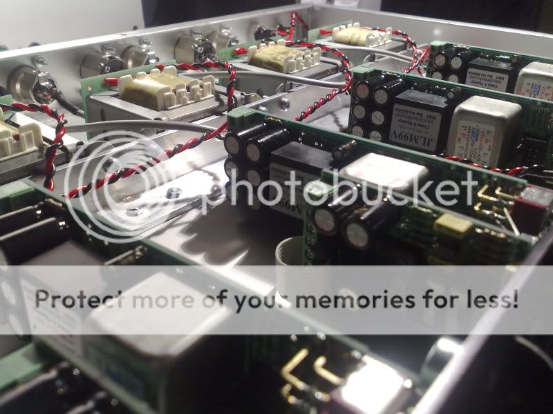
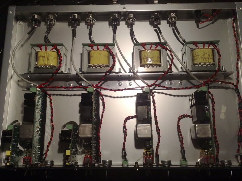
Just finished putting together a 4 channel with VTX input transformers, 99v's and JLM 1:1:1 output transformers
1st two channels have fet di's , 3rd and 4th channel have variable impedance

This is my first major DIY build and was an absolute pleasure.
Joe's boards are excellent to work with and have a great layout

There were a few tricky things to get it to sit inside the case from Elgee (a company that makes rack related stuff here in Australia)
but other than that it was pretty seamless.

put everything together, all voltages were looking good straight away, and every channel works perfectly right from the start.
awesome!!
will be pairing these up with their friends the 2ch dual 99v and doing a live recording at the Enmore theatre next week!!

Thanks to Joe for his help, and of course to the forum for endless inspiration!!

111120091024.jpg


111120091028.jpg


111120091030.jpg


I have alot more pics if anyone is going to build one of these with an Elgee case.
 
Hey Peat,
Nice build ....congrats!  ;) You will be very happy with the sound of these....

I am considering the impedence mod on my BA4 (same case as yours). Did you drill the front panel yourself for the Ch 3 & 4 imp pots? What pots did you use, because I was thinking of using 16mm pots because it is a bit tight in there!


Mac.
 
Hey Mac,

Joe machined the front panel for me, the holes for the impedance pot are 7mm.
You have to use the pot that Joe sells, its a dual 100k log

http://www.jlmaudio.com/shop/index.php?_a=viewProd&productId=73

I think it gives you ~600 ohms in centre position.

 
This is my first post to this forum that i've been reading a lot for 1 month.

I love seeing pictures of what people do so i post some...

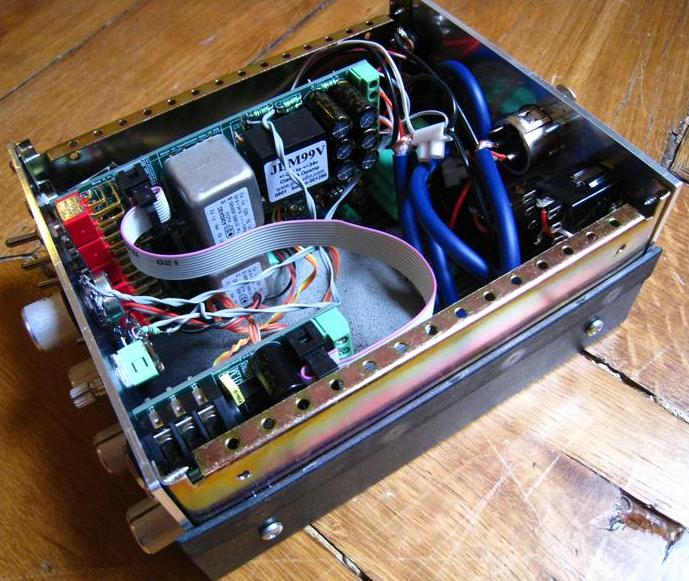
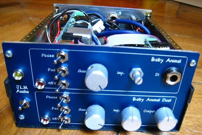
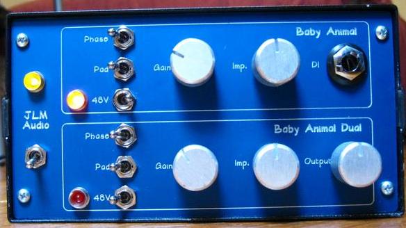
Here is my dual channel preamp.
The great thing is that i could build exacly what i wanted :
. A BAD for my ribbon mic (OEP262A3C + 2* OPA2604) with Impedance pot and dual-position Ouput pot.
. A BA  for my main mic (OEP262A3C  + JLM99v) impedance pot and one DI for my guitare.


Inside, it looks very amatorish compare to the avarage level of building around here. But it's mine... It's finished, it works and sounds good :)
Preamp01.jpg


Shaeffer ag 3mm front panel.
This picture made me realise i didn't paint very well the box in black - it used to be gray..
Preamp02.jpg


Preamp03.jpg


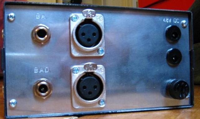
Shaeffer ag 4mm back panel.
Preamp04.jpg


Took me many hours of debugging with my 0 Ohm beeping tester... I really have to learn how to properly solder.

Thanks to JLM Audio for these great Kits !!!

Xavier

 
nice one ixox

love the front panel, very nice work.

looking at the back panel, are you using a separate power supply for each pre, or is it an in/out configuration?
 
Thanks Peat.
And congratulations to you for how you organized the cables inside you 4 channel box...

Schaeffer-Ag front panel designer software with its integrated online order is a very good and easy to use solution (although not very cheap).

The 2 DC connectors is an in/out configuration if ever i build an other 48V JLMAudio Kit.....

Xavier
 
Nice build. Unique, and just what you needed. That's what DIY is all about!

The BAD is fantastic for ribbon mics! I love mine with Lundahl 1538 and two FETBloak discrete opamps. It puts my electric guitar, through a Beyer M160, in its own space in the mix, setting it apart from the bass recorded through my N1272 clone. They blend so well now.

I also tracked a shaker part with it the other day. So fast, so right on!
 
hi guys!
i noticed that my 2 BAs behave in a different way, one has about 8 db gain less.
i don't use them for stereo recordings, so it's not a problem really, but i don't understand why.
they have no noise, hum, distortion. just an 8 db difference.
did some of you have a similar problem?
 
yeah, they both have jlm14 input, 99v opamp, and trafo out.
this is my second pair. the first one was my first project ever so it was soldered pretty bad.
i tried to add a variable impedance pot and i screwed them, so i bought a new pair and built them nice.
i didn't opened them, didn't have time. i'm gonna do it soon.
i was just curious. i mean, they sound both pretty good (i counted gain in pots steps, i'm not a moron)

maybe i wired the input trafo in wrong way, could it be?
or maybe it's the new fet DI i've added,i noticed this on DIs
it's strange, i mean i'm pretty sured about the circuits because i take a good care in build them and i had trouble with my very first one,
so i know some stuff about distortion..
i've put a switch on the trafos outs, and each channel drops about the same voltage when switched the trafos out.
(i measured with a voltmeter)
i swapped the opamps and the pres behave the same way.
no distortion, no hum whatsoever.
impedance pots seems respond in a different way, but maybe i'm wrong because it was just an impression, i didn't tested really.

 
Wow some great pics of well done JLM kits here! My friend has a pair in NY and they sound awesome! I got a case to make my own but had to sell it. Not by choice... But I Will definitely soon. I love the sound of them.

Congrats you guys! IXOX that is a cool one! Perfect desktop animal! And Peat wicked looking rack job. Well done.

John
 
Back
Top