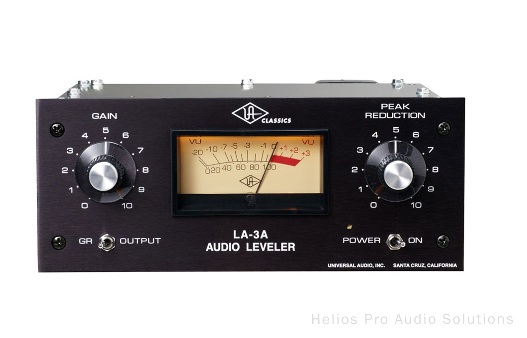
LA3A 500 BUILD

GroupDIY Audio Forum

Help Support GroupDIY Audio Forum:

This site may earn a commission from merchant affiliate links, including eBay, Amazon, and others.
Sorry, this should have all been one post...

Can anyone verify that the BAT85,133 is a worthy substitute for the germanium OA91 diodes? If they're truly just rectifying the VU, then I don't see why not, but I'd love some reassurance.

The cross suggestion was originally posted by Kato, I believe.

Thanks!
 
820k sounds like you're feeding it a 1000V. 15 is more like it.
3 pin header labelled term is for output transformer termination.
Can't verify the diodes.
 
Got the other one sorted out. As suspected, the vias on opamp PCBs didn't like being drilled, so take care there.
 
Nelson said:
Sorry, this should have all been one post...

Can anyone verify that the BAT85,133 is a worthy substitute for the germanium OA91 diodes? If they're truly just rectifying the VU, then I don't see why not, but I'd love some reassurance.

The cross suggestion was originally posted by Kato, I believe.

Thanks!

BAT85 should work fine for VU rectification. The forward voltage is plenty low @ 400mV.
 
peter purpose said:
820k sounds like you're feeding it a 1000V. 15 is more like it.
3 pin header labelled term is for output transformer termination.
Can't verify the diodes.

Thank you, Peter. The resistor calculator I was using wanted the diode's forward current in mA. I was assuming amps so I put in .02, which effectively told it the current was just micro amps. Correcting that, and using 15v as the source voltage, I come to 680ohms for a 2v 20mA bicolor LED and 1.5k for a 2v 10mA single LED.

I still don't understand about the "Term" header, though. My output transformer has 8 colored wires that match the markings on the corresponding pcb holes. By termination, do you mean that there is an option for transformerless output? Sorry if this is a dumb question, but I seem to be missing something. If anyone has a photo of what theirs is hooked up to, it would surely clear things right up.

gemini86 said:
BAT85 should work fine for VU rectification. The forward voltage is plenty low @ 400mV.

Thank you, Gemini. Glad to hear it, those germanium diodes are hard to come by without going international.
 
Thanks, Peter. With a little research, I figured out what you were doing with the terminal header and I've shunted pin 1 to 2, putting the "term" resistor across the output. After which, I also noticed the silkscreen marking that should have told me what to do all along. Just curious, where does pin 3 go? I couldn't find anything it rings continuity to. Is it just a spare pin so you have a place to put your shunt if you want to open the resistor?
 
I may have a problem elsewhere... I've built up a pair of these and need only to widen a couple of holes so my switches function more cleanly and figure out some sort of light gasket for the opto circuit. While doing a little poking around, I've noticed a major difference at the output of the amp that has Q9-11. This is not the amp which has it's output set by RV7, but the amp right next to it. The output of one is a little over 5vdc. The other one is -13vdc. If I swap the amps between the two units, the difference follows the amp, so it must be within those components. I've checked my soldering with a gem loupe and it looks great. The casing of Q11 is very near the output pin, but not touching. Plus I've used "perma-pad" isolators to lift the transistors a bit from the board. I do have extra parts, so I can rebuild whichever is bad. There are so few parts involved, it would be no big deal to just replace every component, but I'm actually not sure which one is wrong. My gut says 5v is right, -13v is wrong, but I don't know. Can anyone shed some light? Would anyone be willing and able to measure the output of that amp on their module? The output pin is clearly marked on the board. Or, is this something that will adjust when I go through calibration? All I've done so far there is to use RV7 to set the main amp's output to 6.5v on both units. I also dialed RV3 and RV36 in to their nominal settings before I put them on the board. Thoughts?
 
Q1... yes
Q2... everyone will vouch for my non existent trouble shooting skills, so can't really help.
If it follows the amp... it's the amp.
I don't have one to test.

peter
 
I rebuilt the amp that read -13v and now it reads +5v. Probably one of the transistors was bad but I didn't look into it any further. Headed to the studio to do the final calibration and finally hear these things! Thanks for all your help, Peter, and thanks to everyone else to chimed in throughout the thread; so many questions I would have had were already answered just by reading through here. Thanks All!
 
Okay everyone I need just one more spot of help! The units are sounding great but the meters aren't working. One was reacting to audio briefly but it was super touchy. When I peaked it out, the needle stayed there and never came down, not even with the power off. The other one never did anything just sat at -20. They do light up. Adjusting RV23 doesn't do anything, even when the one was sort of reacting. The meters are the ones from Peter. I had some LED meters in there which seemed to work but the LED's quickly burnt out as I stupidly forgot to add the forward resistors. Visually, the bulb ones are much more appealing so I'm hoping to get it sorted without resorting to new meters. I have done everything the way DMP mentioned here:

dmp said:
I haven't seen a calibration procedure, but I'll summarize what worked for me.

From looking at Universal Audio LA-3A schems/docs:
RV31 - stereo adj - fully cw nominally (looking from front). Matching two units is accomplished by turning the trimmer ccw
RV28 - HF control - fully ccw for flat: "CW adj of R29 increases the gain reduction circuit for freq > 1kHz"
RV7 - output amp bias - adjust so out pin of amp pcb is 6-7v
RV3 - compress / limit option, 1.3k nominally, adjust to taste I suppose

For the meter:
R24 NI
R13 10k
R22 47k
RV36 - 3.9k
RV23 - adjust to zero meter

Do you think populating R24 would do anything? I don't know anything about VU meters so I'm feeling totally lost on this one.
 
Got it sorted, thought I should post just to tie it all up. So... The problem with the meters was strictly mechanical. I had opened them up to swap out the little plastic backing because I liked it better in the LED ones I'm not using. In doing this, I inadvertently bent the needles slightly outward, just enough so that they touched the clear plastic window. That very slight dragging was enough to stop them cold which surprised me, but considering they're operating from signal levels, I guess I should have realized it as a possibility. Lesson learned: If you open a VU meter, make good and sure the needle is completely free of obstruction when you put the lid back on it. These things sure do sound great! I wish I could keep them! I built these for a customer who had the kits so sadly I now have to turn them over. Peter, if ever you should decide to do another run, I'd be in for at least a pair.
 
Heres some pics of nelsons build he did for me. Got 2 extra faceplates if anyone is interested PM me.


u59x.jpg
aujz.jpg
5rin.jpg
r9j8.jpg
4527_foto1_product_org.jpg
 
OK we still have an issue. It seems like it is thermal related but we are still running tests to be sure. After 20 or so minutes of operation, one channel drops in level by about 5db. The most curious thing is that this happens even when in bypass. With a lot of tweaking, we've managed to get the calibration pretty spot on. The peak reduction is very well matched. If we boost the output to counteract the 5db loss, we still find the peak reduction to be well matched. This leads me to believe the issue is post the optics. This difference definitely effects the gain matching but I think it's just making up for the difference rather than it skewing the amp circuit or anything. Besides, the amp is surely not involved at all when in bypass, right? I think that's the most important characteristic, that it is still there in bypass. I imagine the signal path is very simple in bypass but I don't see the switch in the schematic so I'm having a hard time figuring out what the bypass route is. Can someone please tell me what is in the path while in bypass? I think this one piece of info will lead me right to the culprit. Thanks for any help!
 
Well boys.... In this climate, I'm only going to order as many as are paid for, plus a few extras and I need a minimum of 25.
So if you want them, you'll have to front up £155 GBP per channel, including international signed for postage.

I'll only stick an order in when at least 12 have been paid for. So, from today until the 24th the list is open.
If you pay and we don't reach 12 by then.. I'll refund all monies.

The meters have to come from China, so a minimum of 21 days before anything goes out.

The first six paid for will get free EL panels for the T4B section.

Payment to [email protected]
 
Back
Top