LA3A 500 BUILD

GroupDIY Audio Forum

Help Support GroupDIY Audio Forum:

This site may earn a commission from merchant affiliate links, including eBay, Amazon, and others.
Hi,
after leaving the unit off for some days, i fired it up today to find that the la3a is not compressing. Audio passes through correctly, boost pot works, all the switches work, the meter on i/o works, but there is no compression whatsoever, not on the meter, not on the audio being passed through, the squash pot seems to have no effect and the meter on gr won't move . All the mini boards are correctly socketed. Before I remove the unit and spend my next 2 days checking every connection, has it happened to anyone? Are there places I should check first?

Thank you!

Giovanni
 
I just build 2 LAZ LA3A but have some problems during it’s testing. Bias set at 6.5V. Sounds goes through but when I turn peak knob CW just a little bit then 2-3dB start to compress, unit start to gives me a lot self oscillations. Tuning of R28 don’t effect on this fact. When I turning R31 at minimum it helps to avoid self oscillations but at this moment unit stop to compressing.  All that goes on both channels. Please give some advises how to tune my units for properly action.
 
peskado said:
I just build 2 LAZ LA3A but have some problems during it’s testing. Bias set at 6.5V. Sounds goes through but when I turn peak knob CW just a little bit then 2-3dB start to compress, unit start to gives me a lot self oscillations. Tuning of R28 don’t effect on this fact. When I turning R31 at minimum it helps to avoid self oscillations but at this moment unit stop to compressing.  All that goes on both channels. Please give some advises how to tune my units for properly action.


Try this first to verify your meter is calibrated.

Make sure the LA3A is turned off (top button disengaged) and the Meter button is set to I/O (disengaged).

Also, make sure the Compress/Limit button is on Compress (disengaged) and the Link button is disengaged.

Send a +4db (1.228V rms) 1khz signal to the LA3A and adjust RV36 so the meter reads 0VU.

Next turn it on (top button engaged) and Meter button on GR (engaged) and adjust RV23 so the meter again reads 0VU.

That should finish the calibration process as long as TP1 = 6.5 volts.

Also note that:

RV31 - stereo adj - fully cw (looking from front)
RV28 - HF control - fully ccw for flat
RV36 - adjust as described above
RV7 - output amp bias - adjust so out pin of amp pcb is 6.5 volts
RV23 - adjust as described above


Now send a signal (guitar or bass) to the LA3A with a moderate level. 

With the top button disengaged and the Meter button on I/O (disengaged) adjust the Boost knob until the signal is peaking around 0VU. 

Next set the Meter button to GR (engaged) and adjust the Squash knob until the Meter  is reading around -3 to -5VU which will be close to 4dB of gain reduction. 

*Leave the Link button off (disengaged) and the Compress/Limit button on Compress (disengaged) while running this test.*


I'm looking for someone that has done this build to build one for me.    I have the kit from Peter and all the parts from the BOM's, and had someone lined up to do the build, but they had to back out due to lack of time.  They did verify that I have ordered and received all of the correct parts.

I'm in Nashville, TN , but I could send the parts anywhere I suppose.

Please message me if interested, and an estimate of cost and turn around time.

thanks!

 
(Edited for correctness)

Recently I (finally) finished the pair of units that I ordered.

The biggest problem that people have experienced has seemed to be the meter.  It's a bit of a odd balancing act with series and parallel resistors.  What I've come to the conclusion of, is the provided meter just isn't "right" for this circuit.

I removed the diode bridge on the main board and put a jumpers across GD1 and GD4, replaced the kit meter with one of the 8035 meters from Hairball, dropped R24, and set R13 to 68k.  I won't say it's perfect, but it's way more accurate than anything I could get out of the stock meter.  You won't need the cap across the meter either.

On to calibration....

While DMP provided a procedure for calibrating these, I think his instructions are a little off.  (No offense meant to DMP.)  To recap, here's his procedure from page 11 of this thread:

RV31 - stereo adj - fully cw nominally (looking from front). Matching two units is accomplished by turning the trimmer ccw
RV28 - HF control - fully ccw for flat: "CW adj of R29 increases the gain reduction circuit for freq > 1kHz"
RV7 - output amp bias - adjust so out pin of amp pcb is 6-7v
RV3 - compress / limit option, 1.3k nominally, adjust to taste I suppose

For the meter:
R24 NI
R13 10k
R22 47k
RV36 - 3.9k
RV23 - adjust to zero meter

It would appear that RV28 is "backwards" in relation to the La3a manual (Link)

If you run a 500hz tone into the LA3-500 and set it for 6db of gain reduction and then change the frequency to 15khz, with RV28 set fully CCW you will notice the gain reduction to be about 10-15db greater.

If you want the gain reduction MORE sensitive the HF (the de-essing mode) set RV28 full CCW.
If you want the gain reduction to be "flat" across the spectrum, set RV28 full CW.

Sooo....To calibrate your LA3a-500, Start here:

RV31 full CW
RV28 full CW
RV7 needs to be adjusted so that the output of the output amplifier is between 6-7 volts (I shot for 7v on mine).

Bypass the LA3a
Peak Reduction (Squash) fully CCW
Gain (Boost) fully CCW
Link off
Meter Output
Comp/Lim Limit

Apply a 0db tone (typically around -18dbFS) to the input of the LA3a.  Adjust RV36 to get to "0" on the meter.
Change the meter switch to GR and adjust RV23 to get to zero.


Tone off
Bypass the LA3a
Peak Reduction (squash) fully CCW
Gain (Boost) fully CW
Link off
Meter GR
Comp/Lim Limit
Insert -20db tone (something like -28dbFS from DAW)
you should see -20db on your external meter.

Engage the LA3a.
The output level should increase by 30db (mine hit around 25db)

Reduce the output of your LA3a 10db by decreasing the Gain (boost) control.
Set your tone level to -10db
Turn Peak Reduction (Squash) control fully CW
Adjust RV3 until you see about 14db of gain reduction.

At this point, increasing the input tone level should not change the output level (much).

For stereo...

Tone -10
Engage LA3a
Peak Reduction (squash) fully CCW
Link on
Meter GR
Comp/Lim Limit

This is easier to adjust with an external meter like your DAW but could be done with the internal meters.

Adjust Gain (Boost) until you read 0db on the meters of each unit.
Turn Peak Reduction (Squash) until you read 5db of gain reduction on one of the two units.
The unit with the most gain reduction needs RV31 adjusted until both units show equal gain reduction.

James
 
Thanks James. I'd recently decided the meter is the only compromised element in this project. Otherwise, it's a perfect LA2/LA3 workalike. (Also, I broke the 0 adjust messing with it last night.)

I'm thinking about ordering an 8035, although deep down I suspect it has the same OEM coil inside and other than the internal rectifier it will perform the same as the stock meter. I guess I won't know till I try it.

Thanks for the suggestions!
 
The meter changes I fully stand by.  The only thing that's not per Pete's design is I'm using BAT85 diodes for the DC rectification instead of the OA91's.  It could very well be that the BAT85's  aren't a suitable replacement for the OA91's.  The distortion generated with the BAT85 and stock meter on the output is definitely greater than the jumpered/8035 setup is.

I'm going to rethink the calibration method I posted above in respect to RV31.

The test procedure at the back of the manual is perhaps just that.  A test procedure and not a calibration one.  There's no way you'll get the compression plot on page 13 of the manual with RV31 fully CCW.  So I think I jumped the gun on that.

I'll modify the above procedure when I get some time to test this later today. 
 
It would appear that RV31 and RV28 are "backwards" in relation to the La3a manual (Link)

Interesting. Can you confirm that with a comparison to the schematic? It should be easy to confirm with a multimeter for both trimmers.
It's been a couple years since I built these, but I'd like to go back and and investigate that. Perhaps they do have to be driven a little hard and rv31 would explain that.
 
Hey DMP,

RV28 was definitely backwards (at least with the pot I used).  RV31 was a misunderstanding on my part.

Please re-read my post as I just edited it with a little more thorough procedure for calibrating these guys (including RV3 based on the compression chart in the linked manual).

I just ordered some OA91's to see if that "fixes" the meter problem with the stock kit.  Since they're coming from the UK, it'll be a couple of weeks I'm guessing.

I used Reaper and Voxengo's Span metering plugin as well as an HP Distortion analyzer to check things out.  I know that many people probably don't have access to an audio voltmeter/distortion analyzer so I kept things "loose" in the calibration.

 
The OA91's came in...They don't help the stock meter.

I suggest using the Hairball 8035 meter if you want something that tracks right.  To do so, remove GD1-4, jumper across GD1 and GD4, R13 to 68k, remove R24.  You should be good at that point.  The stock meter uses a lamp for the backlight where the Hairball meter uses an LED.  You'll need to add something like a 390 ohm resistor to one side of the meter light to keep from letting the magic smoke out of the LED in the 8035.

 
So I had my build working... Then I dropped it on the bench while fiddling with the correct mounting hardware for the transformers. I got over zealous and wanted to test it out before I had everything mounted correctly.

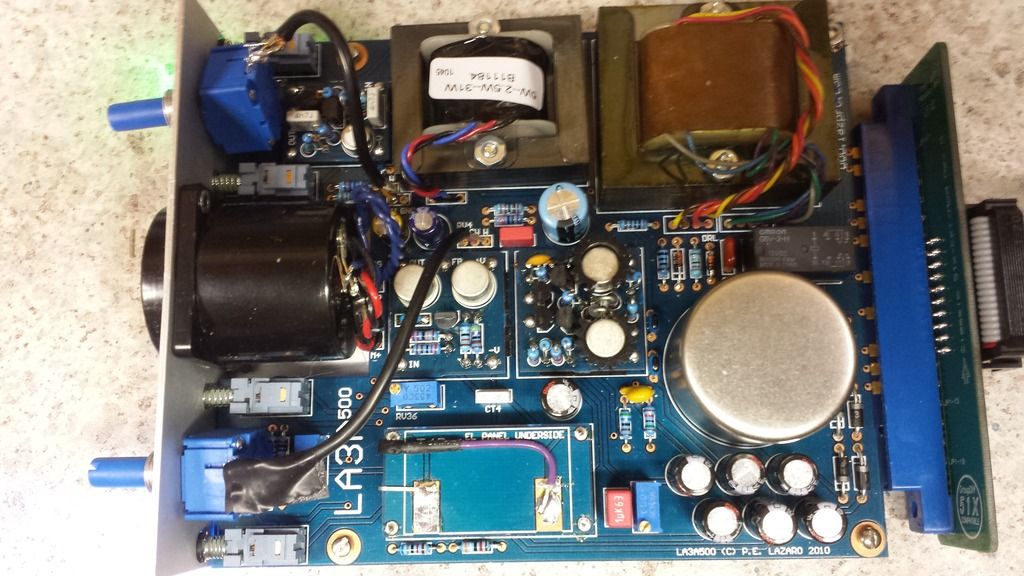
Can anyone provide Voltage measurement at different points on the board, and the autoformer. Its passing audio, but I am not getting voltage to the el panel anymore. None of the schematics I have seen have voltages on them.

Thank you. 

20150314_222204.jpg
 
Will these pots work?
100K-Ohm Audio-Taper Potentiometer : Potentiometers | RadioShack.comhttp://www.radioshack.com/100k-ohm-audio-taper-potentiometer/2711722.html
 
toolboxmuziq said:
Will these pots work?
100K-Ohm Audio-Taper Potentiometer : Potentiometers | RadioShack.comhttp://www.radioshack.com/100k-ohm-audio-taper-potentiometer/2711722.html
Link doesn't work for me, but 100k audio taper appears correct. Check dimensions for fit.
 

Latest posts

Back
Top