M670 compressor

GroupDIY Audio Forum

Help Support GroupDIY Audio Forum:

This site may earn a commission from merchant affiliate links, including eBay, Amazon, and others.
Some nutballs for today:

I might try attaching T2 primary CT leads to ground through two 4.7 mfd caps (value may need to change), moving the C away from the one side.  That would add another potentially helpful balancing mechanism, but might yield worse results than the current plan.  Maybe no different, maybe better. 

May be of interest to also try simply moving 4.7 from one side to CT-ground position, with DC current potential across primary still present, but with an AC to ground path.  I don't expect much out of that one, but might be surprised. 
 
Kingston, thanks for sharing your schematics and observations -- it's highly appreciated (as always).

As for stereo link diodes:
After reading emrr's comments in the Poorman mod/pimp thread (a highly recommended, educational thread, at least for me) I added Germanium diodes (low forward voltage drop) to the first-ever vari mu project on this forum a long time ago and found them to work a charm for stereo linking. Back then I also tried stereo linking at different stages (including before SC rectifier [deaf to stereo] and directly after SC rectifier [i.e., before time constants] with diode isolation) to good result.

Electronics is a hobby to me and I'm hardly more than an amateur, especially when it comes to tube gear, so please forgive me asking: In your schematic, what's the function of the 1N4007 diode, 1M resistor and 10nf in the SC? And why a 1N4007? Wouldn't a low forward voltage drop diode be better here?


The 4uf7 OT cap: Now this is what I call an improvement. Is this image software or an oscilloscope?
Kingston said:
latch-m670fail.png


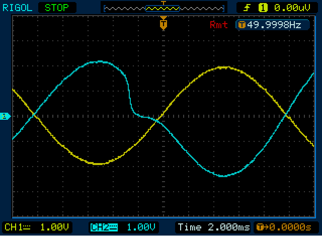
(yellow waveform with cap, blue with no cap)
 
emrr said:
That would add another potentially helpful balancing mechanism, but might yield worse results than the current plan.  Maybe no different, maybe better. 

May be of interest to also try simply moving 4.7 from one side to CT-ground position, with DC current potential across primary still present, but with an AC to ground path.  I don't expect much out of that one, but might be surprised.

These would all be possible improvements, if there was something to dump to ground. The current plan is actually balanced already: the cap and transformer primary (really just an inductor) are in series and both plates actually see the exact same load. Even if that load is a complex jumble of inductance and capacitance in series.

Script said:
Electronics is a hobby to me and I'm hardly more than an amateur, especially when it comes to tube gear, so please forgive me asking: In your schematic, what's the function of the 1N4007 diode, 1M resistor and 10nf in the SC? And why a 1N4007? Wouldn't a low forward voltage drop diode be better here?


The 4uf7 OT cap: Now this is what I call an improvement. Is this image software or an oscilloscope?

The image is rigol DS1052E oscilliscope captured and remote controlled through their ultrascope software. It's pretty handy.

As for the 1N4007, sure a lower voltage drop diode can be used and I've certainly used some schottkys in another project in the past. But I can't detect any practical difference so a cheap one wins. 1m and 10nF are to dump the reverse recovery "snap" to ground. It might have very little practical effect and it's probably pointless with a schottky since they have ultra fast reverse recovery.

Now that I think about it, this is a place for an improvement indeed. I'll take out those reverse recovery hacks and select some modern schottky instead. The ancients needed this reverse recovery hack because their diodes weren't that great.
 
lolo-m said:
And don't be stupid, if the specs you posted are real, just remove the schemo, go and talk to Eva Manley and sell it. Their varimu has got a "tube mastering grade noise floor" of -85 dB. Yours claim -106 or so  :eek:...

To see somebody encouraging to sell a design contribution to an audio manufator in a DIY forum is something new and kind a outrageous.

Why not recommending the Linux guys in an open source forum to sell the stuff to Mr. Gates?
 
fenchelteefee said:
lolo-m said:
And don't be stupid, if the specs you posted are real, just remove the schemo, go and talk to Eva Manley and sell it. Their varimu has got a "tube mastering grade noise floor" of -85 dB. Yours claim -106 or so  :eek:...

To see somebody encouraging to sell a design contribution to an audio manufator in a DIY forum is something new and kind a outrageous.

Why not recommending the Linux guys in an open source forum to sell the stuff to Mr. Gates?

You certainly don't know me !
 
lolo-m said:
fenchelteefee said:
lolo-m said:
And don't be stupid, if the specs you posted are real, just remove the schemo, go and talk to Eva Manley and sell it. Their varimu has got a "tube mastering grade noise floor" of -85 dB. Yours claim -106 or so  :eek:...

To see somebody encouraging to sell a design contribution to an audio manufator in a DIY forum is something new and kind a outrageous.

Why not recommending the Linux guys in an open source forum to sell the stuff to Mr. Gates?

You certainly don't know me !


for that type of topology -100 s/n is quite normal. What is not is Manley
M.
 
-100dB s/n is quite normal for solid state technology
- 85dB is really good for tube technology
Being under -90dB qualify you as an exceptional higrade tube technology.
Even if I don't think Manley stuff is exceptional, the brand is known to do great stuff with great performances. A lot of recognised mastering studios use their tube stuff. They anounce a maximun s/n of -85dB... Reading -106dB on the specs of Kingston comp was quite surprising !
 
To be honest there is some very low level 50hz hum and rectifier crud visible above the main flat line noise floor. When I have time I will post that spectrum too. I'm certain with better transformer shields and better tested rectifier position in the overall PCB/veroboard layout the noise floor could be under 100dBu. I don't think it's particularly exceptional either. Tubes can be very low noise indeed.
 
lolo-m said:
-100dB s/n is quite normal for solid state technology
- 85dB is really good for tube technology
Being under -90dB qualify you as an exceptional higrade tube technology.
Even if I don't think Manley stuff is exceptional, the brand is known to do great stuff with great performances. A lot of recognised mastering studios use their tube stuff. They anounce a maximun s/n of -85dB... Reading -106dB on the specs of Kingston comp was quite surprising !

-86db is not excepional, but not as bad,  if you like manley sound is good too.
I'm talking for my self.
in my exerience, with solid state, a good well filtered PSU  i go for -116db S/N.  my last design, a particular active controlroom is -119db. I own an AP systemone measurement sistem.

in tube topology like that, with well matched tube , with well balanced tranformer, and even a well filtered PSu placed in a proper manner inside the box, as well a good ground plane,  it is not so hard to get -100db. belive me.

anyway these are just electrical measurement what is really metter, as you know, is the sound..

M.
 
HPF: the 2K resistor in the high pass filter section yields the desired effect? Corner frequency is 36.2Hz? Probably I'm missing something here (inductance of the TX?). How about using a pot here with 20R in series?

Edited:
Or should it be 20K (corner freq of 3.6Hz)? I must be missing something.

DESOL RIGOL oscilloscope -- yeah, handy indeed. Thanks
 
Script said:
HPF: the 2K resistor in the high pass filter section yields the desired effect? Corner frequency is 36.2Hz? Probably I'm missing something here (inductance of the TX?). How about using a pot here with 20R in series?

It's a balanced high pass filter. Post number three: http://www.gearslutz.com/board/geekslutz-forum/356482-easy-diy-passive-filter.html

Corner frequency at about 80hz. Very optimal place for a cut.

[edit]

and additional info with even simulation data http://www.groupdiy.com/index.php?topic=38211.0
 
It's a balanced high pass filter. Post number three: http://www.gearslutz.com/board/geekslutz-forum/356482-easy-diy-passive-filter.html

and additional info with even simulation data http://www.groupdiy.com/index.php?topic=38211.0

Epiphanous. Thanks for the links. A lot to read up on.
 
Kingston - thank you for your time and effort in to this project.

I built a PM670 for a friend 4 years ago or so.  It never really worked well.  Balancing left and right wouldn't work with the attenuators I built and linked the 2 channels didn't really work together.
But the inherent sound of the unit was (is) great.
After some frustration with it (and some fried components) I picked it up from him the morning that this tread was started.

Anyhow, I kept the original power supply and added or removed things on the audio side according to the schematic posted on the first page.  I added 2 small boards built on cheap radio shack PC board.  One board has the 100R resistors and the 10uf caps.  On the other board I put all the components between transformers 2 and 3.  It's also got relays to handle the switching. 
Besides that I cut a bunch of traces on the PCBs and stuffed things where I could.  A couple things fit on the underside of the boards.  I did not change Q1.

The end result is really great.  Not much else to say.
I'll add that the stereo link works great and the meters track nicely too.
Thanks!
 
very nice geoff004.

Can you post picture and info about the cut trace and your little PC board.
I like to try this mods too

Cyril
 
creal said:
very nice geoff004.

Can you post picture and info about the cut trace and your little PC board.
I like to try this mods too

Sorry but I don't have any pictures.  I don't have the unit here either - it's back with it's owner.
There's nothing to it really - just as I described.  Cut traces where you have to insert other things.  There are 1K resistors in the 3rd stage, the diode/1M resistor and some other items.  In some cases what was 1 resistor becomes 2.

Then for the boards get some cheap PC board or plastic or anything and go point to point with it.  The number of things to add is minimal.

It's all there in Kingston's schematic on the first page.  Print out both (Kingston's and the original), compare side to side, circle differences and make notes.
 
The bottom of those silentarts boards is very clearly laid out. It's easy to cut traces even if the board is populated already. I do this just by twisting a sharp knife tip at the trace. Dremel is a too powerful tool most of the time.
 
Back
Top