Precocyous
New member
Hi everybody!

I want to recycle an obsolete Sony MDM-x4 “the device” MiniDisc recorder, mostly because I really like how it performs with stacked synths, and as a guitar preamp with returns and also it’s good for the environment in any way. I will try to be as clear as possible, I’m not a native english speaker and I know little about electronics but I’ve been analyzing and reading the service manual of the device and I came to the conclusion that my mods can be done, but I need some help. I’ve made some diagrams, schematics and cutted some snippets from the original schematic in a PDF to give a better idea of what I want to do.
The PDF, here you'll find more snippets with all the modifications and the original schematic:
https://drive.google.com/file/d/0Bzf_13D43EX5dXQ5ZDZGc0xuU0E/view?usp=sharing
The service manual:
http://www.minidisc.org/manuals/sony/service/sony_MDM-X4_service_manual.pdf
I have some questions and I want to know what can be done and what cannot. I want to do the least amount of physical modifications to the circuitry.
1. The Device
The Sony MDM-X4 MkII is a 4 track MiniDisc recorder, it has a mixer module include, that’s the one I want to use. The device I have no longer works due to a failure in the MiniDisc unit. It gives me an -I think- irreparable error, and there’s no technical service for this device where a live, but the mixer is intact and fully working.
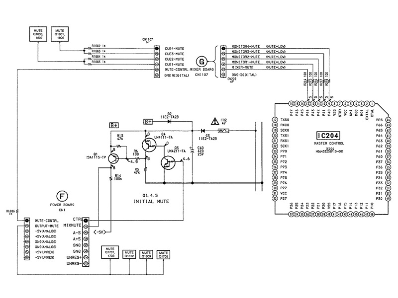
2. The MUTE System (Pages 4, 5 /PDF)
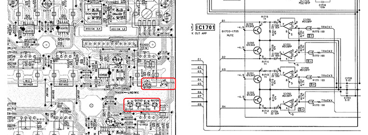
The device has transistors (DTC343) that mutes some of the outputs with a TTL signal (HIGH/LOW). When the MiniDisc unit failed, this signal became always LOW so, always muted.
I’m not going to use the digital parts of the circuit, I’m want to unsold every component that runs the mute circuit (mostly transistors).
Q: Are this transistors essential to the circuit in any way?
Q: If not, can I unsold all of them?

3. The Mixer Sub-Groups (Pages 1, 6-8 /PDF)
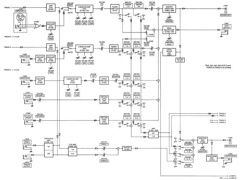
The device has 10 buses, 4 for the groups to record, 2 stereo, 2 aux, and 2 monitors. What I want to do is to disconnect the 4 group bus cables that comes from the mixer board and goes to the A/D buffer and the other that comes from the D/A buffer to the mixer and then connect the 4 group D/A output directly to the playback input in the mixer board, bypassing the D/A buffers and going straight back to the mixer.
The track output will work as a bus-output to use with other recording machines nor gear.
Q: Is this possible?

Modded diagram
4. LINE/MIC switch to Mute channel switch. (Page 2 /PDF)
I think there’s no point routing the new sub-groups straight back into the channels, so I want to use the LINE(Playback)/MIC switch cutting the trace on the board and routing the pin to the closest ground to use it as a mute switch.
Q: Again… Is this possible?
5. Op-Amps.
The mixer module mostly uses M5218 -4558 like- op amps, says the datasheet, but...
Datasheet: http://www.alldatasheet.com/datasheet-pdf/pdf/908/MITSUBISHI/M5218.html
Q: There real differences in performance between those op-amps or they are the same?
6. Extra.
Also, when a signal passes through an inverted op-amp stage it get’s inverted nor non inverted depending if it’s inverted or non inverted at the input, so, if we have an non inverted signal and we pass it through two non inverted op-amp stages...
Q: It still will be non inverted?
Q: No one cares about how the signal inverts across the differents audio gear?
I will be grateful to anyone who’d like to help me with this project. Any suggestions or advice will be welcomed.

I want to recycle an obsolete Sony MDM-x4 “the device” MiniDisc recorder, mostly because I really like how it performs with stacked synths, and as a guitar preamp with returns and also it’s good for the environment in any way. I will try to be as clear as possible, I’m not a native english speaker and I know little about electronics but I’ve been analyzing and reading the service manual of the device and I came to the conclusion that my mods can be done, but I need some help. I’ve made some diagrams, schematics and cutted some snippets from the original schematic in a PDF to give a better idea of what I want to do.
The PDF, here you'll find more snippets with all the modifications and the original schematic:
https://drive.google.com/file/d/0Bzf_13D43EX5dXQ5ZDZGc0xuU0E/view?usp=sharing
The service manual:
http://www.minidisc.org/manuals/sony/service/sony_MDM-X4_service_manual.pdf
I have some questions and I want to know what can be done and what cannot. I want to do the least amount of physical modifications to the circuitry.
1. The Device
The Sony MDM-X4 MkII is a 4 track MiniDisc recorder, it has a mixer module include, that’s the one I want to use. The device I have no longer works due to a failure in the MiniDisc unit. It gives me an -I think- irreparable error, and there’s no technical service for this device where a live, but the mixer is intact and fully working.
2. The MUTE System (Pages 4, 5 /PDF)
The device has transistors (DTC343) that mutes some of the outputs with a TTL signal (HIGH/LOW). When the MiniDisc unit failed, this signal became always LOW so, always muted.
I’m not going to use the digital parts of the circuit, I’m want to unsold every component that runs the mute circuit (mostly transistors).
Q: Are this transistors essential to the circuit in any way?
Q: If not, can I unsold all of them?

The Mute System simplified


The Mixer Board
3. The Mixer Sub-Groups (Pages 1, 6-8 /PDF)
The device has 10 buses, 4 for the groups to record, 2 stereo, 2 aux, and 2 monitors. What I want to do is to disconnect the 4 group bus cables that comes from the mixer board and goes to the A/D buffer and the other that comes from the D/A buffer to the mixer and then connect the 4 group D/A output directly to the playback input in the mixer board, bypassing the D/A buffers and going straight back to the mixer.
The track output will work as a bus-output to use with other recording machines nor gear.
Q: Is this possible?

Modded diagram
4. LINE/MIC switch to Mute channel switch. (Page 2 /PDF)
I think there’s no point routing the new sub-groups straight back into the channels, so I want to use the LINE(Playback)/MIC switch cutting the trace on the board and routing the pin to the closest ground to use it as a mute switch.
Q: Again… Is this possible?
5. Op-Amps.
The mixer module mostly uses M5218 -4558 like- op amps, says the datasheet, but...
Datasheet: http://www.alldatasheet.com/datasheet-pdf/pdf/908/MITSUBISHI/M5218.html
Q: There real differences in performance between those op-amps or they are the same?
6. Extra.
Also, when a signal passes through an inverted op-amp stage it get’s inverted nor non inverted depending if it’s inverted or non inverted at the input, so, if we have an non inverted signal and we pass it through two non inverted op-amp stages...
Q: It still will be non inverted?
Q: No one cares about how the signal inverts across the differents audio gear?
I will be grateful to anyone who’d like to help me with this project. Any suggestions or advice will be welcomed.


