Mic Loading Confusion

GroupDIY Audio Forum

Help Support GroupDIY Audio Forum:

This site may earn a commission from merchant affiliate links, including eBay, Amazon, and others.
I think the Toshibas are still made, although who knows for how long. (2SA1316/2SC3329). I have some bags of each, but if direct pres for ribbons took the world by storm (unlikely!) they'd get used up in a hurry.
 
[quote author="bcarso"]I think the Toshibas are still made, although who knows for how long. (2SA1316/2SC3329). I have some bags of each, but if direct pres for ribbons took the world by storm (unlikely!) they'd get used up in a hurry.[/quote]

Another options are more bags of transistors with higher Rbb, or a small transformer with less ratio.
 
[quote author="Samuel Groner"]
I had started to investigate what such a preamp might look like.
What topology would you suggest? How do you adress input bias currents?

I think the Toshibas are still made (2SA1316/2SC3329).
They aren't...

Samuel[/quote]

Input bias and noise current is somewhat mitigated by a < 1 ohm source impedance.

One starting point is to use one of the transformerless topologies from that thread you posted and parallel up several of the lowest impedance devices you can still find. Probably increase the current density too. The gain and feedback resistor values would likewise need to be scaled down to not degrade overall NF. The imbedded opamp would benefit from adding a discrete driver to deal with these low impedance feedback values. This driver could be mostly class A and inside the feedback loop so pretty straightforward. Probably run this first gain stage at modest p-p voltage swing and follow with a high quality fixed gain stage to get level up to common rail voltages, or not if feeding an A/D directly.

At 1 ohm source I would look at power transistors for lower Rbb but don't feel lucky about process noise and other noise considerations.

Forget about cap coupling the gain resistor. :roll:

JR
 
To start, I would match bias currents using complementary sets. But at that, since we're going to have access to both ends of the sub-1 ohm (Marshall Buck told me 0.3 ohm for one of Wes's units) ribbon, we may as well operate balanced in to begin with. Although this does entail even more devices, since our series noise power doubles over single ended---so maybe that is not such a good idea.

There are also ways to use floating supplies and capacitors other than at the input to make the input current zero, but what you eliminate in one place tends to show up as a pain somewhere else. See for example the common-base MC phono preamp that Aussie guy showed in aXp a while back---I'll try to find the reference.

You do have to parallel for even lower equivalent rbb', and also run currents to where the 'half-thermal" noise of the equiv. emitter R is comparable, but before getting into a lot of 1/f. I think I figured around 13mA per device was fairly promising for the obsolete Toshiba parts---that makes rbb' dominate.* You still need a bunch if you're going to do 3dB NF with that sort of source Z.

I don't think I'd use feedback overall per se in the first composite stage, but probably some other error correction, maybe, to begin with. If the thing is well balanced you are already getting rid of 2nd for the most part.

One could use lotsa FETs but the capacitance accumulates quite quickly and of course it is a huge number of devices to consider, and a whole lot of current. And money, for that matter.


*another unknown with the Tosh devices is parasitic emitter resistance. I ASSume that this is small as well, but haven't measured it.
 
Input bias and noise current is somewhat mitigated by a < 1 ohm source impedance.
Sure, but you never really now what the magnetics does with DC. Probably OK, but it's difficult to be sure.

One starting point is to use one of the transformerless topologies from that thread you posted and parallel up several of the lowest impedance devices you can still find. The gain and feedback resistor values would likewise need to be scaled down to not degrade overall NF. The imbedded opamp would benefit from adding a discrete driver to deal with these low impedance feedback values.
Yes--I've just recently done that for a MC amp and got down to about -145 dBu EIN which is a start, but still short from the desired performance for a ribbon amp. Stability seems to be difficult to ensure though, took me several days to work things out...

I would match bias currents using complementary sets.
That's what I thought as well, but I didn't find a convincing complementary topology yet (which does not need an extra summing amplifier for both halfes).

We may as well operate balanced in to begin with.
Balanced will be convenient as it usually ensures good PSRR and perhaps cancels offsets, but it quadruples the required silicon... :shock:

There are also ways to use floating supplies and capacitors other than at the input to make the input current zero.
Tell me more!

Reminds me of the threads I've read (on another forum) where someone was about to design a 200 pV/sqrt(Hz), 20 dB amplifier with a 0.1 Hz-1 MHz bandwidth...

Samuel
 
[quote author="JohnRoberts"]
At 1 ohm source I would look at power transistors for lower Rbb but don't feel lucky about process noise and other noise considerations.
[/quote]

I used Soviet KT626 transistors (something like BD139). They were made with spiral emitter so had very low noise level on microcurrents.
 
[quote author="Samuel Groner"]
There are also ways to use floating supplies and capacitors other than at the input to make the input current zero.
Tell me more!
Samuel[/quote]

The article by Paul Rossiter for a MC pre-preamp with zero input current is in the September 2006 aXp (I just ran across it while trying to clean up a bit). Some of the analysis is flawed but the topology is interesting and should be adaptable to inputs to bases and to paralleled devices for a ribbon application.
 
> my hatred for the sonic effects of transformers

Many of their ills come from high impedance. Given a 0.3 ohm ribbon and ~~~600 ohm optimum input, we are far away from traditional evils of iron.

Note that the low impedance allows large core. Added capacitance is minor at low impedance, and larger iron keeps you further from the limits of iron.

Though a 0.3 ohm "line" must be short, while any lump in the vicinity of a microphone affects response and pattern. (A transformerless tube input is about an 8-foot lump within a few feet of the mike, which tends to be an acoustical obstruction, before you think about cost, heat, weight.)

I always come to this argument: if a pair of switch-transistors at 2mA can be optimum for 600 ohms (tolerable at 150 ohms), then you need the die-volume of 500-2,000 pairs flowing over an Ampere to optimize near 0.3 ohms.

> We'll see how it works, and if it is practical.

If anybody can, you can.

And 1,000 pairs and a 12V 2A supply is hardly a large investement. (Labor will be a drag,)

But your "hatred" aside: Since the cost and extra setup will be non-trivial, it has to be not just "practical", but "better" (sound-purity or ad-blurb sexiness) than simple iron.
 
>I always come to this argument: if a pair of switch-transistors at 2mA can be optimum for 600 ohms (tolerable at 150 ohms), then you need the die-volume of 500-2,000 pairs flowing over an Ampere to optimize near 0.3 ohms.<

I don't know how they manage it inside the super-low rbb' transistors, but they aren't just proportionally larger devices. But with 13mA the equivalent series noise resistance should be about 3 ohms. Beta can be 500 or more, which makes base current shot noise at mid-high frequencies above 1/f territory about 3 pA/square root Hz. Parallel 10 such and you're getting within hooting distance of a 3dB noise figure, at least at mid-high frequencies. Not as quiet as a transformer, but maybe quiet enough.

Now optimal matching would require about 257 devices and about 3.3 amps, with those admittedly somewhat optimistic parameters, so we move into the realm of pain for mostly specsmanship's sake. And I would suppose that as usual studio ambient noise, mechanical ribbon thermal noise, and air bombardment will dominate a long way before then.

Somebody do it!
 
[quote author="Samuel Groner"]
The article by Paul Rossiter for a MC pre-preamp with zero input current is in the September 2006 aXp.
Thanks, unfortunately I don't have easy access to this writing. Could you perhaps sketch the topology?

Samuel[/quote]

I'll send something in a bit. I thought it might have been accessible on their website.
 
[quote author="clintrubber"][quote author="Wavebourn"]I used Soviet KT626 transistors (something like BD139). They were made with spiral emitter so had very low noise level on microcurrents.[/quote]
First time I heard about such a structure... as in http://www.pat2pdf.org/patents/pat6147368.pdf for instance ? Or had those types something else ?[/quote]

No, it was an ordinary transistor with spiral emitter developed in Tomsk Institute of Semiconductor Devices. It was orange (purple when hot).

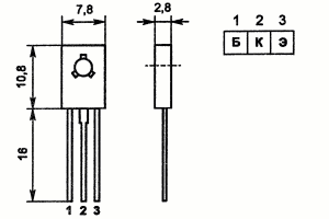
http://www.chipinfo.ru/dsheets/transistors/1626.html

Are manufactured in Bryansk now.

I'm not sure of some other medium power devices from Motorola, TI, Etc... will be usable, I did not try them.
 
[quote author="Wavebourn"]spiral emitter

No, it was an ordinary transistor with spiral emitter developed in Tomsk Institute of Semiconductor Devices. It was orange (purple when hot).[/quote]
Still curious then, how to imagine this 'spiral' ?


BTW, some more curious, who's who here ? :cool:
1,2,3 = B,C,E ?

t4b.gif
 
[quote author="clintrubber"][quote author="Wavebourn"]spiral emitter

No, it was an ordinary transistor with spiral emitter developed in Tomsk Institute of Semiconductor Devices. It was orange (purple when hot).[/quote]
Still curious then, how to imagine this 'spiral' ?
[/quote]

I did not see it; people who designed them told about that. They were not intended to get low noise devices; they made medium power RF transistors, but I used them for mic preamps with great success. They had some in-house name then, something like "Tropa" AFAIR, and later got their official name KT626.

BTW, some more curious, who's who here ? :cool:
1,2,3 = B,C,E ?

Exactly! The rest of Soviet transistors had E,C,B order.

t4b.gif
 
I don't feel so bad now, seeing you guys hash this out. I messed around for a year or so back in about 81 with this, using the big geometry transistors available at the time.

I had a fresh pair of RCA BK-11's that Herbach and Rademan were blowing out for $99 each at the time to use as "subjects".

Never got close to useable results.
 
Back
Top