Mix Bus Compressor from scratch

GroupDIY Audio Forum

Help Support GroupDIY Audio Forum:

This site may earn a commission from merchant affiliate links, including eBay, Amazon, and others.
Well spotted, it's an error on the right channel drawing, the finished circuit has them both positive going.
best
DaveP
 
Hi Dave, Been waiting on your results before ordering iron and other goodies. Does the unit work as intended? How does it track compared to chart in post #10.
Many Thanks Again
 
OK, I have finished the dials and installed the attack and release switches.


The threshold control was very free-running so I fitted a circle of antistatic foam to give it a nice resistance.


I will try to pass audio tomorrow
best
DaveP
 
There appears to be a problem with the side-chain, all I am getting is a square wave with a very short space between squares which does not give any negative DC. The threshold works OK. At first I thought it was an overload on the tube but reducing the input voltage just reduces the square wave, so back to the drawing board. Anyone planning to make this project should wait until I have sorted out the problem.
best
DaveP
 
I have modified the side-chain as the following schematic.


The original side-chain needed to be fed by two diodes, ( I guess to stop cross-talk between channels) I have changed this to two cathode followers to achieve the same effect. Also note the second diode to earth feeding the attack circuit, this is absolutely necessary to get a negative voltage.

So I now have a controlable negative voltage feeding the EF83's but it is not reducing the gain at present, so I suspect that I have to make the circuit more like the original tape recorder schematic for that to happen, we shall see. At least this shows that real life designs take a while to get right.
best
DaveP
 
Last edited:
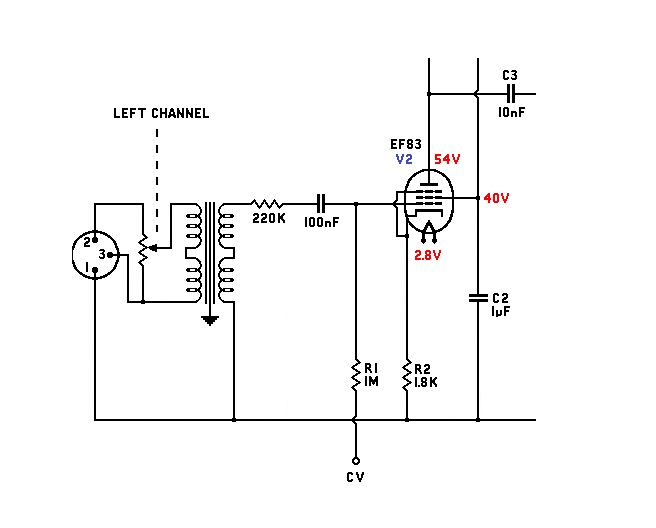
I have made some progress today. The negative voltage is not getting through the 1 M resistor feeding the grid of the EF83. When I short this out, the negative DC reduces the audio input voltage so the output voltage is reduced, but the gain remains roughly the same at about 20x. weird! The EF83 tube spec sheet mentions the source resistance should be less than or equal to 220k, but it is often more than this on many circuits as there is usually a resistor from the preceeding EF86, I am not sure how much this affects things.
best
DaveP
 
OK, I have added a 220k resistor in series followed by a 100nF cap and the negative voltage is no longer lost down the 1M resistor.


I think the negative voltage was shorted out through the IPT and now the input cap is stopping that happening. This makes the circuit more like the taperecorder circuit and it is possible to have up to -9V on the grid now although it should not need that much in normal use.
A good days work!
best
DaveP
 
Back
Top