MK47 PCB tube mic kit - build thread

GroupDIY Audio Forum

Help Support GroupDIY Audio Forum:

This site may earn a commission from merchant affiliate links, including eBay, Amazon, and others.
I still can't figure out why my 2.3k dummy resistor is burning up but since I only need it for a moment while adjusting voltage

While testing, i had a 25W, and it was getting very hot too after some time,
this is only for checking purpose, so as long as all the rest is ok, i guess all is good then....

Better have higher wattage Dummy loads for whatever i think...
 
some more voltage tests:

Mic/PS #1: 
B+ with mic attached:  105V
B+ with dummy load:  102V

Mic/PS #2:
B+ with mic attached: 111V
B+ with dummy load:  106V
So, I need to modify PS#2 to bring the pot within range.

Difference between the two mics on the same PS:  3V

I have no obvious heating problem with the dummy resistor.

 
Well the idea behind it if i get it correctly is that when pattern is on one of the position,
you should not have 105V on Pattern OUT (normal), and on the other, you feed 105 volts
across a 14K and the Relay, wich has also a resistance that should be
about 12K i believe, and so having about 48V at it.
So for knowing that you should switch the pattern that sends the 105V to the relay,
or just check the relay you'll get the point, if you check the Voltage across the 12K resistor when in off position,
then you have about half voltage , get it?

But if you made some tweaks as you said before than this would be off i guess.

EDIT: Seems I got it wrong   

EDIT EDIT: not that much actually...

just my 2 cents ...
in fact it´s a simple voltage divider .
kirchhoff says : U = Ur1 + Ur2  (105V = U(above 14k ) + U(above 12k)) equals : 26k = 105V ; 12k = ? =>
(12*105)/26 = 48,46V

total load would be 26k paralled 2k3  =  2k11 thats what gives you the 105V .
 
hmmm ok !
Actualy I had a connection problem so now, I get 48V at the center pattern switch pin
Can someone explain me why when I switch the pattern On I get 110V at the same center pin ???
I think that is not correct

I think I'll leave it all for tomorrow ....

Thanks Zayance for your messages by the way :D
If I got it right You were wrong when you said you were right to say that you were wrong ! ( or something like that :D )

Good night all !
 
If I got it right You were wrong when you said you were right to say that you were wrong ! ( or something like that  )

yep  :)


Can someone explain me why when I switch the pattern On I get 110V at the same center pin
I think that is not correct

Mic attached? As reference to ground? means Pin 2 and pin3 of Output Voltage terminal?
Or when yu check HT when Switching Pattern ON Pin 1 and 3? If that then it's correct also, you get a
slightly higher HT when Relay gets in the circuit if i get it correctly....


@nashkato: yes, that's what i meant, with relay, it's a simple voltage divider.
well that's what i understood about it...
 
in fact that's Mic attached
Pin 2 and 3 of power terminal
and Pin 1 and 3 the voltage raises too ! ( and it shouldn't ) to 110V
I mean if there is a 12K load in the circuit ( the relay ) it should keep almost the same voltage than when the dummy 12K is in the circuit
So the HT voltage should not raise !
something seems to be wrong !
 
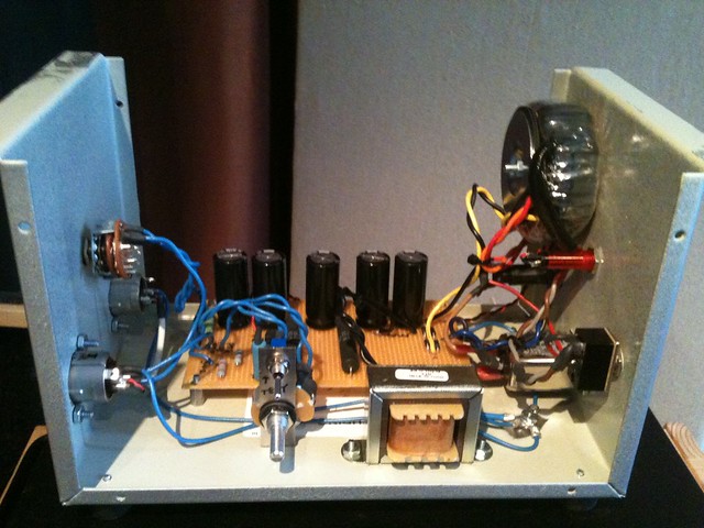
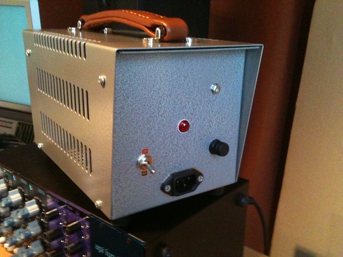
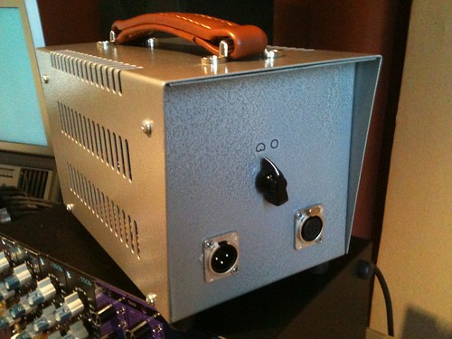
Well, I added a 300 ohm resistor in series with the 1.5k feeding the pot and now I'm able to get 105V no problem. I did find that the voltage in my apartment jumps around from 118V to 121V and this causes my power supply to jump around too. Anyway, I'm calling this done until I get my MK47 built and test it for good. I built it out of a heavy duty steel Hammond case and painted it with hammertone spray paint. The size is really a bit much for what's needed and it was a pain to drill through but not bad. I got the "leather" strap from ebay/china for like $7 or something.
6330501526_e53807d4f4_z.jpg

6329752643_da6ef5b565.jpg
6330509420_e1568bff90.jpg

 
Yeah, but it looks badass.  I think I used the next size smaller Hammond case.

Nice.
 
Ok ! My fault !
I had a bad wire contact

but still can't make the 6.3V light work !
tried to plug a LED and it worked
how can I make that work ?
 
but still can't make the 6.3V light work !
tried to plug a LED and it worked
how can I make that work ?

If you're talking about the PCB connection?
It's made for a LED not for a Light Bulb. (as on ioaudio's schematic)
Light bulb needs a 6.3VAC (if your light bulb needs that)
So if you got yourself the Power transformer from Tube Town,
then you're good to go.

If you tried the light bulb on the PCB connection, then it must be fried.....
 
success!!!  both psu's are passing 105V and both mics are passing audio.  the mics are dead quiet, but have a bit of an 'am radio' quality to them.  likely culprits are a) lack of burn-in, b) hi-z sections need attention, c) i'm unaccustomed to the 'u47 sound,' or d) crappy test headphones.  we'll see how they behave after 24 hours of power.  here's a shot of my supply boards, decided to throw together a layout for mental stimulation and ease of racking.  i'll be building more tube mics in the near future, so i figured i'd do a big ol' psu box to keep me warm in the iowa winter!  if anybody's interested in the layout/bom for etching, i could easily get that sorted out.

only thing i might change in the future would be to move the rectification off-board and closer to the toroid, it's fine now but i could see ac hash getting into my audio as i add more supplies to the case.
 

Attachments

  • IMG_0444.JPG
    IMG_0444.JPG
    43.9 KB
Thanks! It would still be a pile of parts without a couple of your posts, that triad toroid does nicely with 1K's throughout. I opted for the BeezNeez K7's in Skylar's bodies, though I'd like to try some of Dale's design down the road.
 
I LOVE the BeezNeez.  They definitely should not sound like AM radio. 

I like my Chuck D M7, too. It's a little less vivid, but has a nice quality to it. It glows rather than sparkles.


Here are a set of sweeps comparing the capsules. Same mic electronics, PS, and body in the same set up.  Line voltage changes and warm up times might affect overall levels a little bit.
->This doesn't represent the true frequency responses, only the relative responses of the capsules to each other. 
 

Attachments

  • capsule comparisons.png
    capsule comparisons.png
    104.7 KB
So I'm finishing my MK47 now but I have to ask, what exactly is the purpose of having capsule connections run through the glass tubes? Am I supposed to solder the capsule leads on the bottom part? Would there be anything wrong with soldering the capsule leads directly to the relay pins?
 
monkey said:
@grantlack, can you expand on what you mean by "am radio" sound?

It's midrangey, not quite nasal in quality but bothersome in the same way. Seems like the LF is rolled off as well. The tonal quality is consistent across both microphones, so it may be something induced in the supply rather than the microphones themselves. Inductor proximity?
 
Interesting. I have something going on in the mids as well, which I think of as sounding "pointy" which seems like maybe distortion at certain frequencies. I notice it mostly on vocals, and then more on certain syllables (and not sibilant ones, per se).

My supply is sort of improvised, so that seems like a more likely culprit than say the capsule or amp. What would inductor proximity  do?
 
glimmertwins said:
bobine said:
Yeah, but it looks badass.  I think I used the next size smaller Hammond case.

Nice.

Just curious - would that be the 1453B - the 6x6x9.5 or the 1453C 7x7x11?
It's the 6x6x9.5. Be warned that the thick steel can be a bit difficult, but it's do-able.
 
Back
Top