MK47 PCB tube mic kit - build thread

GroupDIY Audio Forum

Help Support GroupDIY Audio Forum:

This site may earn a commission from merchant affiliate links, including eBay, Amazon, and others.
Hi there,
Finally built a pair with dale capsules... amazing fat smooth sound thats clear!
I have a slight issue, my pot fully decreased my mic takes about 111.6 dc, is this a problem with the extra 6.6 volts?
Sounds nice hot haha!
G
 
Hello all,

Having a challenging time here...

PSU seems to be fine

Microphone is not!

Not a peep out of it as far as the capsule goes
If you move the tubes a little or change the position of the multimeter probes there is some scratching that comes through the speakers
However, tubes do not get warm (will they start to glow at all?) nor does the resistor mounted in the base of the body
Measure 348VDC across B+/B-
Grounds seem to check out and solder joints have been checked.
Resistance across heater pins is approc 90 ohms

If anyone can recommend a methodical way for troubleshooting this I would be appreciative.

Thanks
Mac
 
Hey,

that sounds like the tubes are not loading the circuit. try a fresh pair of tubes. I highly recommend the ebay dealer that does lots of ten tubes for £30 or so.

does your PSU work with the dummy resistor? does it put out around 105-110V with the dummy resistor?

If the answer to the above question is yes then it will probably be your tubes.

Also, and this is important, check that the traces on the mic PCB are intact. Has one of the traces broken?  This happened to me and it took me ages to realise that the MIC PCB was a little flimsy.

regards

Michael de A


ps yes the tubes will start to glow within 5 seconds of turning on the PSU
 
Thanks Michael

Will try new tubes and see

Suspect it is a broken trace...have btpassed two areas already where my butterfingers created issues

Take care
Mac
 
It turned out to be traces 2 and 5 where they come off the main pcb to join the smaller semicircular one.
Despite having good solder joints the resistance was off the scale-the trace had lifted right off the pcb and must have been fractured
More point to point wiring and the output dropped to 105V and the tubes began to glow!
Nice sound from the beginning with very low noise (once the microphone body was put on) and no popping at all.
Currently have Equinox capsule but will put in a BeezNeez K6 next time it is taken apart (or perhaps a Beez Neez M7)
Cheers everyone, thank you for all your help. Particularly to iaudio, Zayance and Chunger

Taker care
Mac
 

Attachments

  • 20130920_210331.jpg
    20130920_210331.jpg
    531.9 KB
Just completed my MK47 power supply using a Zayance pcb and Dan's case.  All is working but my output voltage varies.  After setting it to  105.0 volts, it will wander around this reading as much as +/-1 volt.  I checked the input and it doesn't change more than .2 volts.  Anyone else see this?

Regards,
Jeff
 

Attachments

  • MK47ps1.jpg
    MK47ps1.jpg
    862.8 KB
Aaronrash said:
Are these kits still availible? I would love to build one of these

Check here:

http://www.groupdiy.com/index.php?topic=35667.msg437839#msg437839

http://www.groupdiy.com/index.php?topic=50694.0
 
Getting close to finishing my psu, but i could use a little help with regards to getting the voltages right. I used zayance's pcb and the triad vpt230-110. I'm in the us, 122v out of the wall. checked the voltages this morning with the dummy resistor load- i get a range of 294-280 measuring at the "105v" terminal. at the center of the pattern switch i get 45v and measuring from gnd to either the yellow or black wires coming off the toroidal into the 200v in i get 187v.
nothing caught on fire or exploded at least. 
 
finally finished mine but ****** up the connection of the pattern switch (switched the terminal connections of the center pin and the 12k resistor ond zayance pcb) on the psu....realized this after 3 hours burn in of the mic

and i was wondering why i could not hear a difference with switching the pattern  ::)

any possible damage due to this error?
mic was passing audio but really noisy and the occasional pops and clicks (used a 6w 1k5 heater dropper resistor and 10w resistors in the psu)
 
Ok, got the test resistor in the right place. Now I get a range of 84v to 70v. Hmm, any ideas what I messed up this time?  I basically built it like chunger's with the zayance pcb, triad toroidal and choke, 1k pot, 3x 1k 10w resistors, etc.
Here's some photos:
10476181225_3df4da59a0_o.jpg


10476180275_e5549d9103_o.jpg


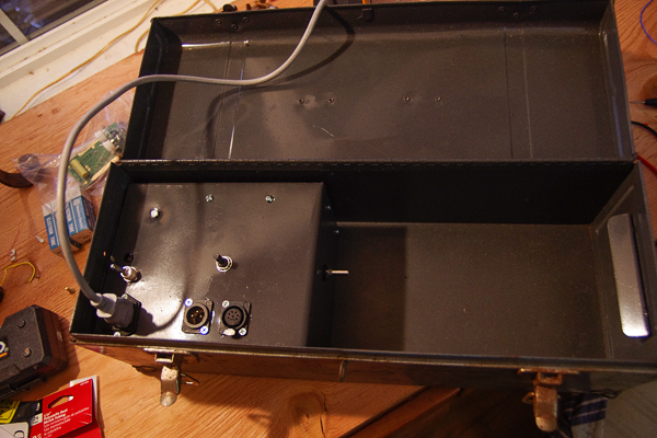
It's going to go in this high-tech psu case:
10476192394_e15500598b_o.jpg


Like this:

10476374763_26f6a63b69_o.jpg


There should be enough room for the mic, shockmount and cable on the right-hand side. Once I get this voltage issue figured out, just gotta wait for chunger's gt-2b's to come in.
 
Ok. This time when I measured the voltage, it kept going up slowly, starting at 84v and I got it to settle down at 105v. Cool! i need to get those ali clips for my dmm....
Kinda sad that I'm done.  :'(
 
unfortunately the mic is still way too noisy to work with...psu without anything attached is silent, psu with cable only attached silent as well...as soon as i connect the mic
even without turning it on there is noise  :(
 
read the whole thread again and tried a different grounding scheme....still horrible noise

can somebody show me a clearly understandable working way on mic, psu and cable???

atm i have connected pin 7 in the cable to the shield on both sides, in the mic pin 7 to b- (pin 3), pin 3 and pin 7 united in the cable on the mic side.
in the psu my iec ground, pin 7 and pin 3 and the xlr pin 2 are going to the 0v connecor
 

Attachments

  • Foto.JPG
    Foto.JPG
    141.8 KB

Latest posts

Back
Top