MK47 PCB tube mic kit - build thread

GroupDIY Audio Forum

Help Support GroupDIY Audio Forum:

This site may earn a commission from merchant affiliate links, including eBay, Amazon, and others.
Just solder it to the + voltage rail directly above the delaminated pad.  Double check w Max on that resistor value.  You want to end up w 20V at the heaters and this resistor is what drops B+ to that 20V. 
 
Thanks! I thought so myself, but wasn't 100% sure. The crackle is still there, but since it's new tubes I'll wait a couple of days before pushing the panic button.

John
 
It's done!  8) ...(almost ;))

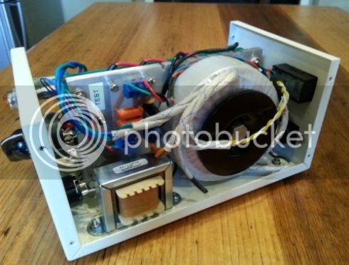
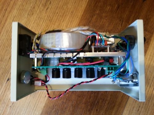
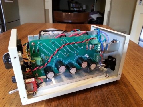
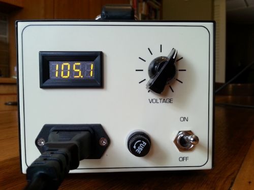
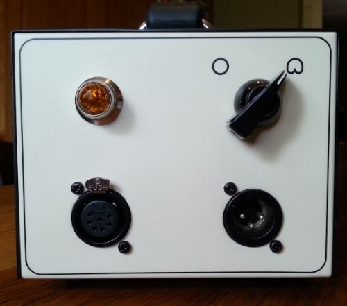
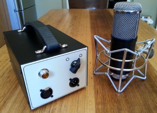
Here are a few pics of my MK-47 PSU and Mic.


The PSU is based on a Zayance PCB and Antek 230>200/6.3/6.3 Transformer.


My final resistor values were Choke +1k + 1k + 630ohm and a 500ohm pot. This gives me around a 10v B+ adjustment range with 105v usually around centre. I tested with a 2.4k resistor. My mic seems to be a slightly higher load than that.


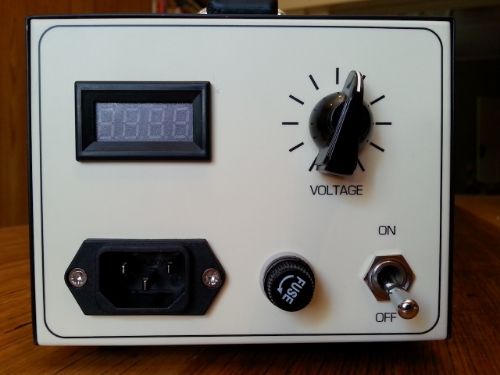
I mounted the pot on the back of the case with a knob so I could adjust the voltage easily. Mains voltage drifts around quite a bit where I live.


To monitor the B+ voltage I installed a 4 digit voltmeter. I did this by making a small PCB to rectify one of the 6.3V AC secondary outputs of the Antek transformer to a DC power supply for the meter .  I also included a trimpot on on the PCB to adjust the meter for accuracy. (see earlier post for details). I can report back that there are no noise issues with this setup. The PSU is rock solid and quiet.


In hindsight a 3-digit meter might have been better as I've found the voltage drifts around by about 0.2v constantly. I assume this is due to mains drift. The voltage can also take sudden drops of around 0.5v when a household appliance on the same circuit kicks in eg. fridge or coffee machine in the kitchen where I took the photos.

I don't suppose it matters much in terms of function, but it can be slightly annoying with the digits constantly changing. It would have perhaps been better to be ignorant to the minor changes and be reassured by the display of a solid 105v!

The other 6.3v secondary powers the jewel light - amber colour to match the voltmeter LED's. It's a little too bright so I will swap for a 12v globe to tame it a bit.


The PSU case is a 4" x 5" x 8" cheap from China one, found on eBay. Everything just fits inside with not much room to spare. I stripped and repainted it to suit my colour scheme. The text and markings were applied using water-slide decals before a final coat of satin clear. Everything is mounted to a piece of 6mm aluminium angle which doubles as a heat-sink for the resistors. The unit runs just warm to the touch.

I also stripped and painted the mic body - a GT-2B from Chunger. The satin-black finish is fantastic but caused grounding issues between the retaining ring, main sleeve and head-basket, resulting in hum problems. I had to scrape some unseen paint away to get a good contact and now it's quiet as can be. There were a few pings from the WE 408a tubes to begin with but after a few hours burn in they are perfect.

I also foolishly attempted to polish the head-basket rings and upright bits and re-plate them with nickel. It turns out there is some aluminium or something that doesn't like electroplating inside the bottom ring of the head-basket. My electroplating guy told me it just wouldn't take the nickel and it showed signs of etching and blackening ???. The top ring and uprights, being brass, plated fine and look great. I ended up painting the bottom ring to match the body - a look I think I actually like.

After testing with a cheap Chinese capsule, I installed a Thiersch Blue Line capsule, which so far sounds fantastic, detailed and smooth. I have a session on tonight with a great male vocalist. I'm looking forward to hearing the results there.

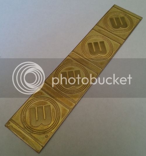
The last finishing touch I want to do is to add a custom mic badge in matching colour scheme to indicate the front side of the mic. I took some of my design cues from the Neumann badge. I etched the design into some 19mm x 0.8mm brass strip using the same method I use to etch PCB's (laser printer 'toner-transfer' method). It took about half an hour to etch in Ammonium Persulphate. Now I just need to have them polished and nickel plated, paint the etched 'lower' section black and bend to shape.


Apologies for the marathon post, but I am so pleased with this project, I just had to share!

Finally, many thanks to Max, Zayance, Chunger and Matador for providing such a great project. It is now the jewel of my studio!
 
Hi guys,

my build of mk47 is now completed.  For PSU i used Zayance PCB!
The Problem is that i can´t get to trim the HT pot B+ Voltage to 105 VDC, when PSU is connected to the mic! The maximum i´m able to get is 102VDC.
When i just connect a dummy load of 2.2kOhm instead of the mic to PSU, i´m able to trim to 105VDC.
I tried already different pairs of tubes burned in for at least 48h(all jan6028) - but nothing changed!
The mic is actually passing audio through....
What could be the problem?
THNX
Tom
 
What are the specs of your transformer?  You probably just need to drop the resistance a little.  Do you have the parallel 330ohm on top of the 660 in the last slot?  If not, adding it should drop the resistance to around 220 or so and give you some extra adjustment room. 
 
Category 5 said:
What are the specs of your transformer?  You probably just need to drop the resistance a little.  Do you have the parallel 330ohm on top of the 660 in the last slot?  If not, adding it should drop the resistance to around 220 or so and give you some extra adjustment room.

Thank you very much for your help, problem fixed!!
Tom
 
ioaudio said:
102VDC is close enough...

On my build I can get 105VDC but it drifts over time by +/- ~0.5VDC but never over 1VDC. I keep the mic and PSU in a stable environment and it performs perfectly with the drift. I've been cracking open the case once a week to verify voltage levels but this gets to be a little tedious. I'd like to keep the lid on and maybe check the voltage once a month or so. Is there an acceptable drift range before the mic's performance is affected?

Thanks!
 
Remember that in a passive design output voltage is directly related to input voltage.  You are likely only seeing minor fluctuations in your line voltage which are not a big deal and nothing to obsess over.
 
I enjoyed my mic for about a year after the build but it has since displayed intermittent noise. It's a static or white noise sound that pops in only for short, maybe 0.5 second bursts every 10 seconds or so. It's not super loud but loud enough to be audible to me and my clients. I tried cleaning the high impedance area and even replacing the tubes but the noise is still there. Anyone have any suggestions? I love this mic, it sounds amazing but this issue is making it unusable at the moment.
 
jordan s said:
I enjoyed my mic for about a year after the build but it has since displayed intermittent noise. It's a static or white noise sound that pops in only for short, maybe 0.5 second bursts every 10 seconds or so. It's not super loud but loud enough to be audible to me and my clients. I tried cleaning the high impedance area and even replacing the tubes but the noise is still there. Anyone have any suggestions? I love this mic, it sounds amazing but this issue is making it unusable at the moment.

Sound like you are using western electric tubes.  I have found them to become this way without warning and have yet to uncover the cause.  I recommend trying some rca, Philips, GE or Sylvania 408a tubes and your problem will likely subside.  The hi-z section is floated in both designs so contamination of these parts is unlikely to be the culprit. 

Some members have achieved better results by switching a sand-bar type dropper resistor with the aluminum sinked type but I have found the problem to arise even with this type of dropper resistor.

I hope some of this helps. 
 
Thanks for the tip, Cat5. The original tubes that I had the problem with were Phillips. I just put some Western Electric tubes in and have not noticed an improvement. I think replacing that cement resistor is the next step.
 
there's so little it could be. Unlikely to be the dropper.

If i were a betting man i would say it were the valves and maybe even their seating.

Michael
 
jordan s said:
Thanks for the tip, Cat5. The original tubes that I had the problem with were Phillips. I just put some Western Electric tubes in and have not noticed an improvement. I think replacing that cement resistor is the next step.

The WE tubes sound like that when new.  They pop and crackle and have static.  After a 48 hour break in (running signal through mic) they quiet down but in my experience they still can make noise randomly. 

Before anything try another set of Philips and see if things improve.  They are quieter from the get go but even they may require a good burn in to achieve best noise performance. 
 
jordan s said:
Thanks for the tip, Cat5. The original tubes that I had the problem with were Phillips. I just put some Western Electric tubes in and have not noticed an improvement. I think replacing that cement resistor is the next step.

I would also suspect the cement resistor - there have been a few cases where this resistor has been the culprit. Replace it with a aluminium housed resistor.

-Max
 
Is this do to non-linearities with the rise in temperature?

I'm trying to understand why one would work better than another if both are wire wound, white soap bar vs aluminum sunk resistors?  Maybe the aluminum dissipates  heat better?


ioaudio said:
jordan s said:
Thanks for the tip, Cat5. The original tubes that I had the problem with were Phillips. I just put some Western Electric tubes in and have not noticed an improvement. I think replacing that cement resistor is the next step.

I would also suspect the cement resistor - there have been a few cases where this resistor has been the culprit. Replace it with a aluminium housed resistor.

-Max
 
Back
Top