vinylwall
Well-known member
duy_hoang said:Hi,
in my case, it was stuck in cardiod mode like Category 5 said. The faulty solder pad was the one of the lower relais pin (see picture)
Hmmmm. My build is stuck in cardioid too.... :-\


duy_hoang said:Hi,
in my case, it was stuck in cardiod mode like Category 5 said. The faulty solder pad was the one of the lower relais pin (see picture)
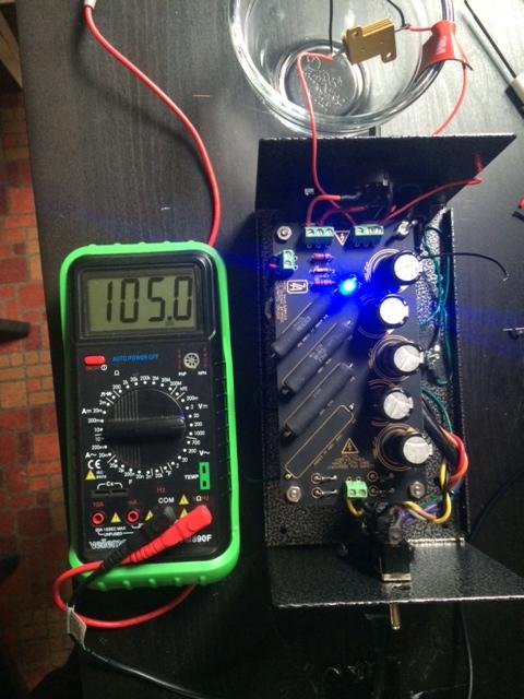
ioaudio said:Check first if your pattern switch is working: It should show 0 Volt in cardioid and B+ (unloaded) or 48v (loaded) in omni position.


![Soldering Iron Kit, 120W LED Digital Advanced Solder Iron Soldering Gun kit, 110V Welding Tools, Smart Temperature Control [356℉-932℉], Extra 5pcs Tips, Auto Sleep, Temp Calibration, Orange](https://m.media-amazon.com/images/I/51sFKu9SdeL._SL500_.jpg)