I can draw a jack circuit and switch if it will help.
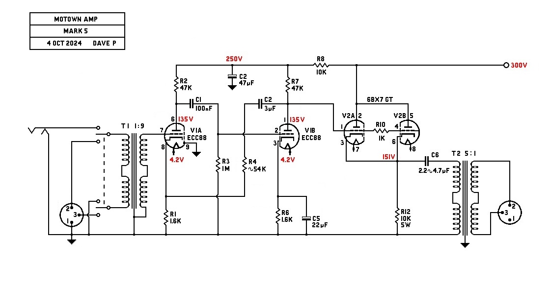
For T1 I would use a mumetal case 600:50k from RS
https://uk.rs-online.com/web/p/audio-transformers/2106352?gb=s, but there must be others that are similar. For T2 I would use a 2.5W edcor 15k:600 but people may turn their noses up at that! This thread has discussed the transformers in some detail. Look Midnight, trying to get all the mounting holes predicted may not be wise, because that chassis is small and you may have to move the transformers around to avoid hum pick up. Look how they mounted that choke for instance.
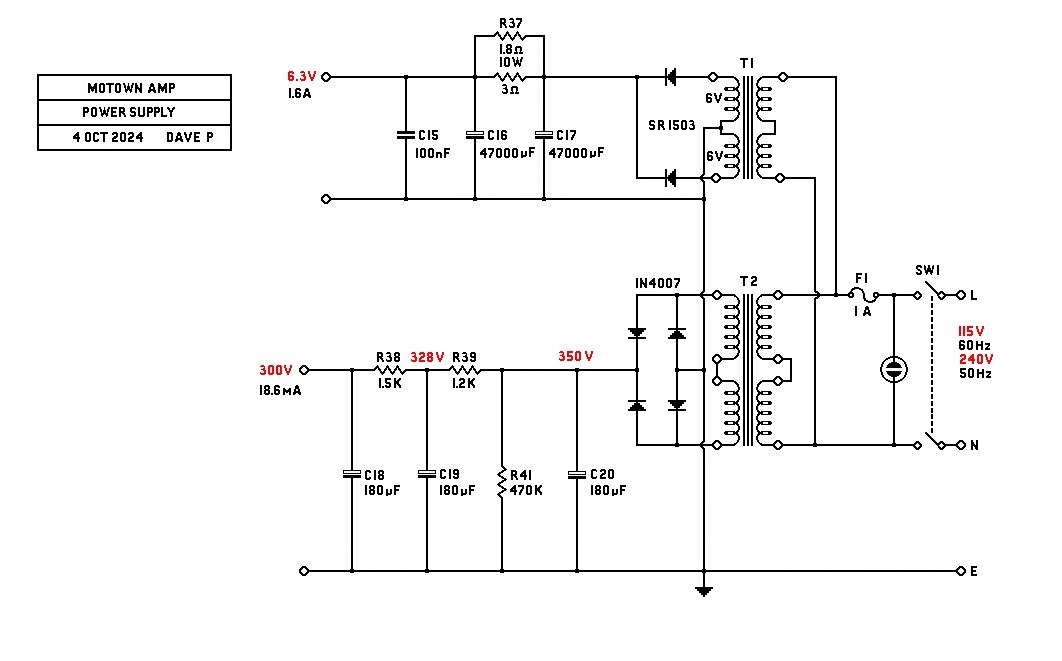
I can draw a suitable power supply but I can't predict the performance of your chosen power transformer, adjustments will probably be necessary.
I only use 0.75W metal film resistors for ruggedness and lowest noise.
best
DaveP