Motown Direct Amplifier-inspired Preamp?

GroupDIY Audio Forum

Help Support GroupDIY Audio Forum:

This site may earn a commission from merchant affiliate links, including eBay, Amazon, and others.
Continuing my calculations:-
To find the operating points for the tubes we need to work backwards from the output. We are given that clipping started at +27dBm (600 ohms).
This is 17.35Vrms on the secondary, therefore there must be 5x 17.35V on the primary which is 86.75V . As the CF has a gain of 0.9, the drive voltage must be 86.75/0.9 = 96.4V. I have previously calculated the gain of the two tubes with NFB to be 30dB, therefore the input voltage to the first tube must be 30dB less or 96.4/31.62 = 3.05V at clipping. From this we can say that the first tube will clip at 3.05 x 2.828 =8.62Vp-p, dividing this by two gives us the cathode voltage =4.31V. If the IPT is 1 : 9, then the input to the amp would be 4.31/9 = 480mV which sounds like the right ballpark to me.

A cathode voltage of 4.3V puts us in ECC82/ 6SN7/ 12AU7 territory.

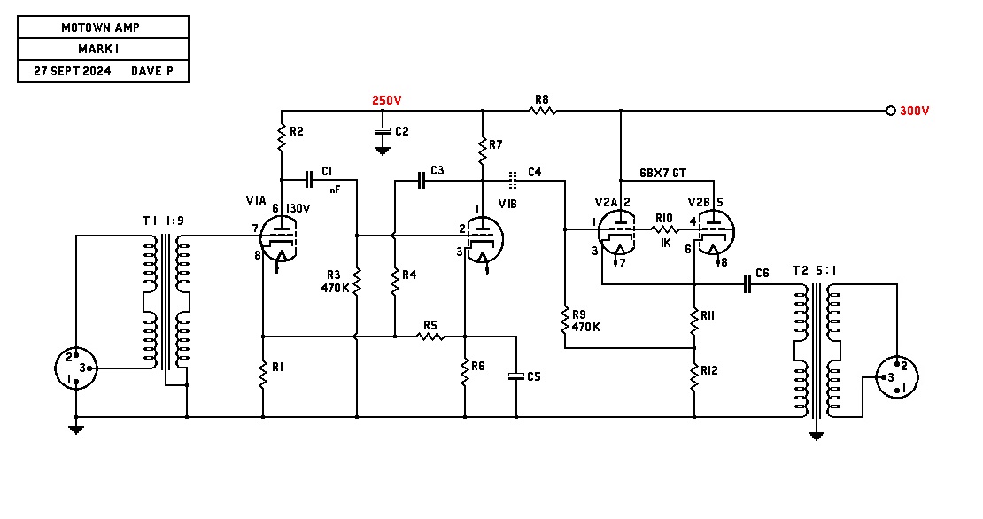
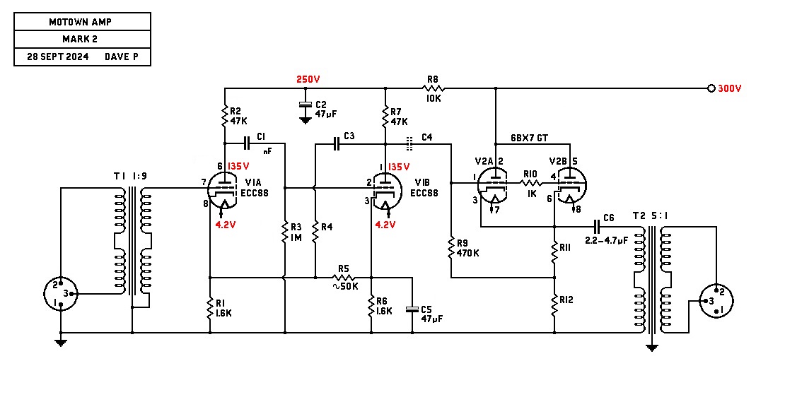
I am drawing up a schematic based on the V72 but with triodes instead of pentodes.
best
DaveP
 
I have tried to chart various tubes with a Vk of 4.2V and a gain un-by-passed of 17-18 and I cannot find one.
The gain is from 8 to 13 only, so I guess that DC feedback is needed to increase the current in order to get 4V on Vk
best
DaveP
 
Possibly a cathode follower driving the WCF?

here is the scratch pad with an LA2a type circuit on the top, looks like too much gain unless you knock it down with dividers and NFB,

the bottom drawing is a Marshall type cathode follower feeding the WCF, and some NFB. this would cut down on the gain as the second part of the follower has close to unity gain,

i have an RCA 6BX7 on the way from evilbay,

there is also that Jensen line driver with the 6AU6 driver which might be interesting
 

Attachments

  • m1.JPG
    m1.JPG
    409.7 KB
Last edited:
I have never understood the fascination with the White follower. Yes, it has an incredibly low small signal output impedance but its main advantage is that it is push pull so we save a lot of quiescent current. Its biggest problem though is it has unity gain. This is why I prefer to use an SRPP output stage. It has the advantage of being push pull and it has a decent amount of gain. Its downside is higher distortion but the NFB takes care of that.

Cheers

Ian
 
I have seen a version that has a phase inverter driving a WCF or SRPP, I forget which,

If the reissue is just using one 6V6, that says that the original did not use a white cathode follower, if they are using the same circuit.
 
Last edited:
This is how far I have got in making a V72 type circuit with a 6BX7 cathode follower.
Please note that it has both ac and dc feedback.

I will gradually fill in the circuit values and update as I go.

C4 may not be needed if DC connection is possible.
C6 would probably be around 2~5 uF and should be chosen to give a flat response with the resonance of the chosen OPT.
best
DaveP
 
Last edited:
This is how far I have got in making a V72 type circuit with a 6BX7 cathode follower.
Please note that it has both ac and dc feedback.

I will gradually fill in the circuit values and update as I go.
[I will gradually fill in the circuit values and update as I go] -- Good Deal!!! Looking forward to a completed schematic!!!

[ac and dc feedback] -- AC/DC were known for their feedback!!!

/
 
UTC HA 113 would work well for this project with the 200 mW level,

This dealer says there is a Cinemag output xfmr in there, probably the 2840 which would suggest a follower circuit,

12AT7 tubes are listed on another site, I bet the original used 12AX7's, maybe they wanted lower gain to compensate for the 6V6 being used in place of the 6BX7, strap the 6V6 for triode operation and you could probably use 12AX7's,

https://ardasuppliers.com/en-lv/pro...hSIj6XxkwOpBQVBjRk0q0PSi0W_fLhzTYNcfORXW9zE2d
 
Last edited:
Found a gut shot, non invasive,

Cool on the tube socket shock mounts !

The 6V6 being that close to the open frame xfmr worries me,
 

Attachments

  • tumblr_p25s2xtXYj1txvfmdo1_1280.jpg
    tumblr_p25s2xtXYj1txvfmdo1_1280.jpg
    170.6 KB
This topic sort of reminds me of an interview with Pino Palladino.
They are sitting in a studio and Pino has this beautifull fretless bass.
At some point the guy asks.. "can I play it ?"
"Yes sure" Pino says...
The guy plays this wonderfull bass and says .. "it sounds like me"

Pino replies "What did you expect ?"

:D
 
Yes that does sound different .

They use to split her voice, one channel was normal. The second channel was sent through a filter to extract the upper freqs of the hi end, then they would boost the crap out of it and combine it with the normal channel. That's why she had that shimmer on her vocs.

Years later somebody put that idea in a box and called it the aural exciter, although I think the method used was a bit different.

They had tricks for trying to make AM radio sound hi fi.
[Years later somebody put that idea in a box and called it the aural exciter] -- Back during the 1980's and 1990's, I remember reading more than one article mentioning that the guy who had started APHEX had built himself an audio preamp from a kit. He eventually happened to notice after awhile that the audio signal going into one of the inputs sounded differently than the same audio going into the other inputs (i.e., switched line-level inputs). So, he decided to back-trace his wiring of the preamp and then discovered he had made a wiring error when he had assembled the preamp.

I am assuming that his preamp kit may have been similar to one that I once owned that had the usual complement of stereo inputs, such as: TAPE 1, TAPE 2, TUNER, AUX, PHONO, etc. What this guy discovered as he back-traced his wiring was that the audio-signal of one of the inputs accidentally got routed into and through the phono-cartridge of his turntable. Since, for whatever reason, this audio had a pleasant and unique "shimmer" to it, he then began to experiment and research -- WHY -- the audio sounded "better" going through a phono-cartridge!!! The end result of his experimentation and research became the "APHEX AURAL EXCITER".

Anyway.....that's my story and I'm sticking to it!!!

/
 
Nice gut shot CJ. Looks like a regular octal rectifier tube. According that ChatGPT the output tube is a 12B4A (another double triode) and the mic pre tube is an EF86. Not sure what the middle on is but a 12AX7 would be my guess.

Cheers

Ian
 
Nice one midnight. I have been using ChatGPT to find out what tubes are used. It says the first three (from left to right in your chassis) are EF86, 12AX7, 12B4A

It gets confused about the fourth tube (the rectifier). First it says it is a 6X4 (which is a small B7G tube), then it says it used a semiconductor rectifier, and lastly it thinks it is a 5AR4/GZ34 (which seems most likely).

The mains transformer (rear right of the chassis) seems to be a Hammond 309JX if my reading is right. Output transformer is a Cinemag and probably physically identical to their CM-2810 model.

Cheers

Ian
 
Nice to see CJ getting stuck into metal bashing for this topic over on the Lab!

Here is an updated schematic, the only tube that would do the job is an ECC88/6DJ8.

I calculated that the gain of one tube un-by-passed times the gain of the other by-passed must equal or exceed 30dB. The ECC88 does just that leaving room for at least 20dB of NFB. Both tubes run at 2.5mA so the HT dropper passes 5mA x 10k =50V drop. The 47uF cap on V1B is 3dB down at 4Hz. (RK//rk =800ohms).
best
DaveP
 
Hammond 369JX pwr xfmr

Cap is a JJ

But don't want to copy ACME, trying to make a 1 off of the original.

Sweetwater has the tubes listed as EF86, 2 ea. 12AT7, 6V6GT.

The EF86 was not on the original but added as a mic input for more versatility.
 
Last edited:
The mains transformer (rear right of the chassis) seems to be a Hammond 309JX if my reading is right. Output transformer is a Cinemag and probably physically identical to their CM-2810 model.
[The mains transformer (rear right of the chassis) seems to be a Hammond 309JX if my reading is right] -- You may need to get a new prescription for your glasses as there weren't any "309JX" transformers on the HAMMOND website. However, there was a "369JX" mains transformer as shown below:

EDIT: -- I just took a closer look at the photo of the chassis and its mains transformer and.....it is indeed a "369JX"!!! YAY!!! In any case.....this proves you do need a new prescription!!!

(I'm kidding!!!).....

EDIT-2: -- It took me so long to finish my first edit that CJ posted the correct transformer model in the mean time!!!


1727540252899.png

>> I have attached the "369JX" datasheet for your review.


1727540952004.png
-369JX -- 50 ------- 500V C.T. @ 69ma. --------------- 50 ------- 6.3V C.T. @ 2.5A ---------------

And, here is the link to the entire HAMMOND "300-Series" of power-transformers, should the "369JX" not be the correct one:

https://www.hammfg.com/electronics/transformers/classic/300

/
 

Attachments

  • HAMMOND -- 369JX Power-Transformer Datasheet.pdf
    272.5 KB
Last edited:
Just a note, the 6BX7 is mentioned twice, once by by ptown and once by the acme guy as being the output tube on the original unit. This is on page 6.

It is also mentioned by ptown that the output stage has no gain. This would indicate a cathode follower. Since the 6BX7 is a dual triode, it seems logical to use it as a white follower aka LA2a, the high plate current would not be conducive to using the tube in parallel.

A regular cathode follower could have been used if the tube was used for 2 channels at once.

The choke is a Hammond 157G, as mentioned on page 1.

These long threads are conducive to info being lost and repeated.
 

Latest posts

Back
Top