IT WORKS!
The "proof" of my operational A*P*I 2520 variant made using LTSpice, Eagle and a CNC machine:
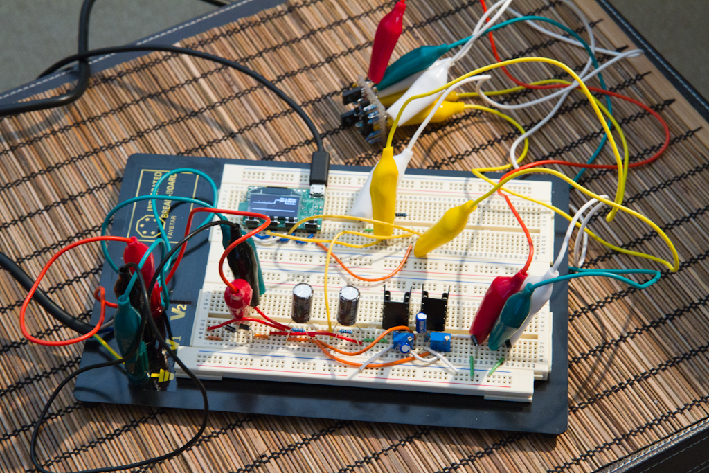
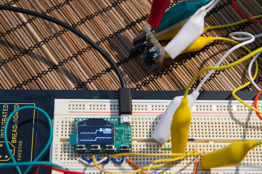
Here is the test setup, you can see that I'm not winning any awards for shielding, which is part of the idea.
If the opamp is stable enough, it should be able to live with situations like these.
Note the opamp in the background, the breadboard PSU provides the +-16V needed, and an Xprotolab super small digital storage oscilloscope:
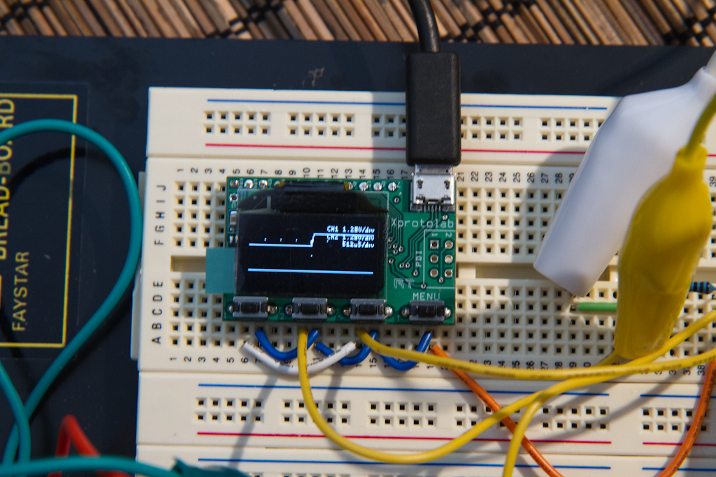
That was before switch on - the top trace is channel A and shows a 100Hz square wave test signal. Channel A is looping back from the Xprotolab waveform generator set to negative pulse display reset - so it holds a single "step" of the square wave.
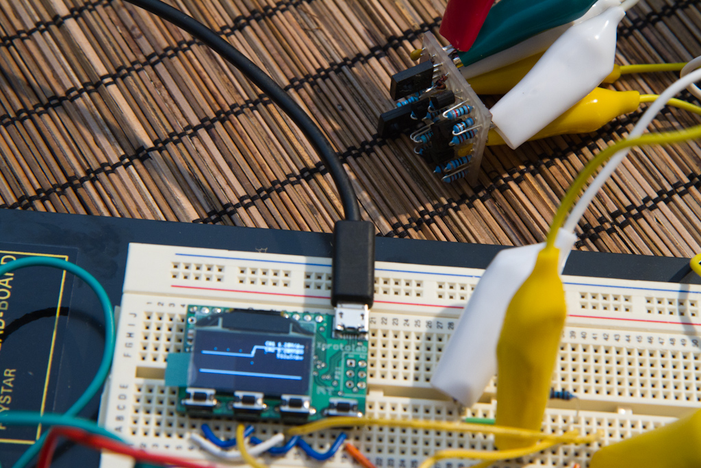
Note that the bottom trace is totally flat, since the amp is not yet turned on, and is therefore effectively ground ( first image Xprotolab is in focus, second image opamp is in focus ):
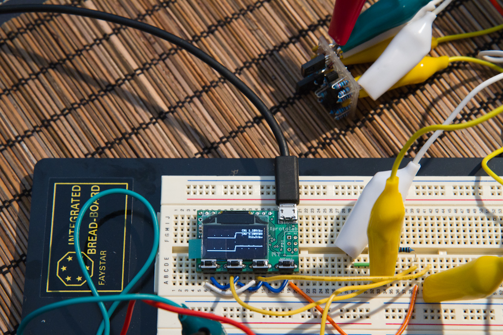
Now I turn it on, using it as a DC buffer of gain 1.
Using typical operational amplifier circuitry ( since that's what it is! ), you connect a dummy load of 1K at the output pin ( the closest I had on hand to 600ohms - the resistor is in frame to the very right of the above image ), then connect the - input to the output pin for full negative feedback, and then connect the + input to the test signal, i.e. a unity gain buffer with 100% negative feedback:
Then BOOM!, the B trace ( lower ) on the Xprotolab, is a copy of the one above. The opamp is therefore stable as a unity gain buffer in this case and works beautifully ( right image is 15mins later, so it hasn't exploded or gotten warm by this point ).
Just think, all of that to get the same output as input.... Seems not like much hey? ;-) Next step is to test it's amplification abilities....
This was the output opamp design for my custom audio compressor, next step is the input amp, which is completely different, then, if that works, I'm 50% there. The rest is the dynamics section with a voltage-controlled amplifier chip that sits between the input and output opamps.
I already have a A*P*I 2510 input amp design I've refactored into a 2520 sized package ready to also be CNC'ed out for testing.
So, at least in a super controlled test, it would seem that my 2520 is kinda working - sweet!