My little Beast (Updated - Panel Time)

GroupDIY Audio Forum

Help Support GroupDIY Audio Forum:

This site may earn a commission from merchant affiliate links, including eBay, Amazon, and others.
You know, I remember getting into serious trouble back in the day for playing too much Megaman. But being
an android with an arm cannon and all these funky gadget levels? Lord, took my cake ;)
 
livingnote said:
But here's my idea for where to take this thing long-haul:

Code:
In L+ Buffer     ->     VCA  \                                         /  Out L+
                               THAT Reciever  ->  CnB  ->  THAT Driver  
In L- Buffer     ->     VCA  /                                         \  Out L-

In R+ Buffer     ->     VCA  \                                         /  Out R+
                               THAT Reciever  ->  CnB  ->  THAT Driver
In R- Buffer     ->     VCA  /                                         \  Out R-

This assumes that the input signal is fully differential, with no common-mode component.

livingnote said:
This way I surmise we can have a serious whack at CM where we
need it, getting VCAs to cancel each other's distortion and doing standard
laundry service.

Even if all VCAs are perfect clones distortion-wise, (or can be trimmed to be so), this only cancels even-order distortion.

JD 'naysayer' B.
 
My gut feeling is it would be better to determine which components on the path are responsible for the "signature" sound and "trim the fat". Personally, I see no point in inventing hot water, but rather to enhance the signature sound - with slimmest circuitry, the right tweaks, best possible layout and rails decoupling. I know from experience that it is possible to simplify circuits and optimize their working environment so that it delivers much better than f.e. the factory unit.
 
That makes sense too. I was just thinking along the lines of the ultimate build by Keith - if SSL
went off and worked with phase-flipped VCA's what would be the point of debalancing everything,
then sending it through the VCAs as +/-, then summing that (basically debalancing again)
and then balancing everything right after that...
 
You know, for a pimped unit, I'd start from the basic blocks first.

a) input - I'd take a simplified version of ssl9k line input (stripped of the servos and taken un-bal'ed directly after the first opamp - can be done before anybody says it cant be done) which is an abnormally pimped up superbal with a supersecret inside-fb-loop trick that allows use of small foil caps @input instead of electrolytics. Perhaps I'd use 1 or 2,2uF wimas there instead of 100nF ... should be checked for flavor with listening tests and not with analyzers

b) i'd clean-up the vca signal path, possibly using a 10uF wimas there. Wasn't it a common practice to parallel the vca's. That would be simpler to do and possibly closer to the sought-after vibe?

c) for outputs, either THAT chips or some smart dual-opamp trick like rane 124...

d) I'd RC decouple the rails - just like I did in summo (this works and is cheap) and power the channels and SC in a quasi-triple-mono way.

As said, I'd start from the basics, to derive a good, powerful and punchy "engine" first. Ading blends, trafos and SC filters is the easy part (or "creative" part for those who fall on hooks like that)...

Adding light-shows will polute the environment...
 
a) sounds good - gonna try that

b) where the 10µ wimas? Parallel vcas installed in design through 202 footprint (custom subassembly board thinkable)

c) That in the output in souped up version, definitely.

d) RC decoupling ?achieved through CRC filter (installed) or did you have something different in mind

Light show has separate trafo & is galvanically isolated in this rev - I just love my light show so better do it right ;) Signal
is decoupled by a cap when it changes grounds for metering.

But I really have to try this four-lane thing out while I'm at it - I was thinking along the same stripping down lines when
I thought it might be best to debal after the VCAs themselves with THATs because no point in debalancing twice in a
row, then again perhaps exactly that makes sense because first you're not shooting stuff from the line into the VCAs
and so when the VCAs cancel at least a part of each other out it's only that and not a mishmash of everything...don't
know for sure...
 
Speaking of parallel VCA subassembly boards....

I remember seeing a kitform or pre assembled 202 type VCA on the internet once,  IIRC, with 2x2 antiphased 2180´s. I bookmarked it back then, but since my PC broke down, I can´t find it again.

Today I spent a couple of hours googling for it, nada.

Does anybody here know where to find it ?  I'd like to DIY a few of those to replace my 202XTC's, and it might be something cool for everybody here too.
 
Oh that would be cool - then again designing a little pcb that does that shouldn't be
the problem. However, I did design the two shorter boards to basically be optional
in the circuit - stick them in for ultimate or leave them out for standard config. If
a subassembly with two antiparallel 2180s in the 202 footprint is available then you
could conceivably drop the two shorter boards and still have an ultimate, with the
2180 I sometimes wonder if going all in like back in the 202 is just sonic nutpicking?

(Then again I do know a nutpicker or two who get 25 of those little nuts together and
blow your ears off with the result)...
 
Hahaha,

Yes,
Well, I haven't heard a comparison between an antiphased VCA array and a normal parallelled VCA array, so I don't know what the real result will be. But from what I have read, is that the antiphased one has less of that typical VCA sound.
So, partly, it's just curiosity, but on the other hand, I don't really like the sound of the SSL busscompressor (but I do like the way it glues the mix !), so....... It could be something really cool.

And besides the GSSL, if an antiphased 202 VCA array indeed sounds better, I might replace all the 202's in my mixer as well.
 
You know I've been thinking...what about getting a tranny together that has
nice saturation characteristics, and then finding some opamp that really can
do voltage and give the tranny a run for its money? Does anyone know of
an opamp that can drive like +/- 24 Volts?
 
http://jlmaudio.com/shop/index.php?_a=viewProd&productId=23

how about 34v? (minimum 24v)

or the 16v version (can run on 24)
http://jlmaudio.com/shop/index.php?_a=viewProd&productId=24

orrr this one too.
http://jlmaudio.com/shop/index.php?_a=viewProd&productId=70
 
Thanks!

Yeah that last one looks pretty cool. My thinking was that you can get this big
electron cannon and shoot at the tranny, saturate and balance in one and then
pull the gain back down to humane levels at the output. Could you concievably
do this and keep the output's ability to float?

Yesss and Segor here in Berlin has it too...nice. One thing that's pretty cool
is to abuse a Siemens Haufe off some V275/0 amp.

Actually I even still have a pair of Haufes that I pulled out of a big broadcast
patchbay, now that would be a can to juice...
 
You could use a standard "+/-15V" opamp (OPA132 etc) with boostrapped rails (so it will run at higher voltage supply) with added AB or class-A output stage (2 pairs of BD139/140) - or a diamond buffer.


pros: you could design for safe thermal operation (cooling) at prolonged operation (slamming), and it could be cheaper than some snazzy DOA..

cons: slightly fiddlier than a generic DOA, hardly a plug-n-play vibe...


...but you like to draw pcbs anyway so in the end it's a matter of preference ...
 
Looks like this will be a piece of work. So many good ideas, makes me want to do a
lot of prototyping. Not quite got the time atm, but thanks for the input - I guess at
this point it makes the sense to first build just the run-of-the-mill SSL and then
go off from there when it's confirmed working.
 
sure.

For consideration: The buffered/flying rails approach could be divided in two main groups:

a) where the rail voltage is higher than max. allowed for the opamp (fe. you have +-24V or higher rails and want to use a standard +-15V specced opamp)

b) you have +-15V (standard) rails and want headroom vaguely similar to f.e. +- 28V rails. This is OTOH a "gross & crude" method and _requires_ that some care is taken with rail decoupling because it _will_ slam the signal at the rails - just like RCR bootstraps work in an audio power amp. (the cost for the luxury here is five 1000uF elcos and 4 pcs. 2watt resistors).

IOW, both can be done, it's relatively simple and can be seamlessly integrated with a "power" AB class output stage.


DOA vs frankensteins ... pick your poison.
 
Alright - Panel Time!  ;D

Or "how to abuse an otherwise unsuspecting branch of the industry for
your DIY":

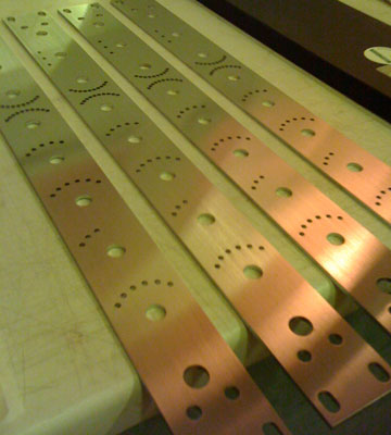
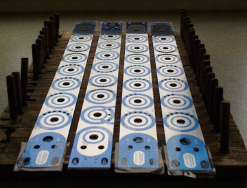
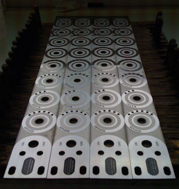
The blanks, lasered 3mm chrome steel, ready for lamination:

paneletch1.jpg


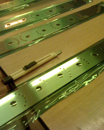
Photoresist laminated on:

paneletch2.jpg


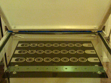
Big vacuum exposer with the photoplots...don't screw up
registration or you get to do it all over again:

paneletch3.jpg


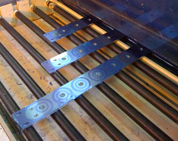
You can see the latent image as it goes into the developer:

paneletch4.jpg


Developed, and meticulously retouched by hand:

paneletch5.jpg


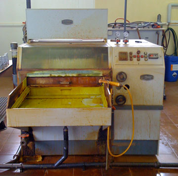
Now comes a machine you can do some major screw-ups with:

paneletch6.jpg


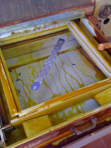
Board juuuust fits in the carrier:

paneletch7.jpg


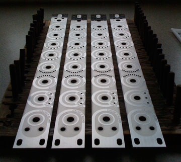
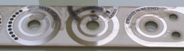
Etched and stripped:

paneletch8.jpg


Makin' a mess with backfilling:

paneletch9.jpg


All cleaned up - now just have to remove the ferric stains
with something like stove cleaner and it's a wrap:

paneletch10.jpg


Yeah  ;D

What I love about it is that you not only have total creative
freedom, it's chrome steel you're working with...feels very
different from Alu (though I love anodized Alu too).
 

Latest posts

Back
Top