important Information For All M49 and 269c builder
the psu pinout connection shows that pin 3 is the cable shield lift channel with the jumper that should be by default installed on the psu , unless a specific cableshield scheme is used and that pin 7 is the Audio Ground ,
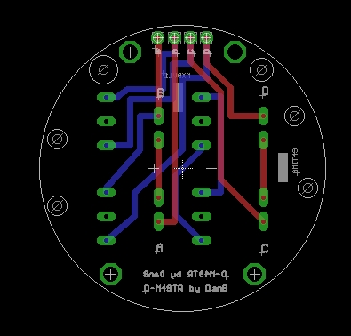
on the M49 Mic pcb as per the original numbering the pin 7 is actually the shield from chassis and the pin 3 is the audio ground ,
since the 2 points are linked on the pcb they are basically the same but special attention must be taken to actually take into account for this properly grounding the mic and cableshield as the number are reversed on the mic end ,
take special attention to ground loop while grounding the shield of the mic cable ,
Side Note: For those having a polarity that is reversed for a known or unknow reason , remember that you can swap the wire inside the psu at the xlr output connector swapping wire pin 2 and wire pin 3 will reverse the polarity of the ouput.
the same PSU can be used for the M269C build but note that the difference is that pin 3 is the calibration input on the mic pcb not the shield ,
there is a pad on the 269 pcb labeled Cal on the mic pcb. Always have the original schematic of the mic when building as all the numbering on the mic pcb always follow the original numbering on the schematic as opposed to the psu that will always stay te same for both mics 49bc-269c ,
the remote pattern on the M269c is like the original as well that is you have to switch on the mic pattern and then on the psu to get the poper pattern , ( see schematic) the use of a linear pot can be used in both configuration for the pattern ,
Best,
Dan,
I went to update the PsU schematic with proper labeling of the output pin of the psu and also did this little table that will help explain
Cabling connection From PsU https://cdn.groupbuilder.com/groupdiy/u/39511/58d0281993e53.jpg


