Neumann U47FET Clone: D-U47 FET Microphone Project PCB Build thread

GroupDIY Audio Forum

Help Support GroupDIY Audio Forum:

This site may earn a commission from merchant affiliate links, including eBay, Amazon, and others.
TillM said:
Yes I take the Tbone sct700 body, which is the same.
The mount is the smallest you get from Thiersch.
Should be 52mm high.
Don’t forget to take a small acrylic plate under the holder.

Thank you for your answer!
where did you buy the acrilic plate?
 
I do it on my own ;)
https://www.wir-bedrucken-shirts.com/acrylglas-rund-2-mm-staerke-durchmesser-von-10-120-mm.html?MODsid=28081445bc6803a2a87aa88dc0fd3824

I take 12mm and drill a 3mm hole in the middle.
Its just because the M7 don't like metal plates.

Here is a sound sample.
Thiersch M7 Redline, Sowter 1303.
It's use it just on my kick. No processing. Recorded through my Hairball Lola with gar2520 DOAs
https://www.dropbox.com/s/6gm9a4t7z0u15w0/Kick%20Out%20U47FET%20with%20Thiersch%20M7%3ASowter.wav?dl=0
 
TillM said:
I do it on my own ;)
https://www.wir-bedrucken-shirts.com/acrylglas-rund-2-mm-staerke-durchmesser-von-10-120-mm.html?MODsid=28081445bc6803a2a87aa88dc0fd3824

I take 12mm and drill a 3mm hole in the middle.
Its just because the M7 don't like metal plates.

Here is a sound sample.
Thiersch M7 Redline, Sowter 1303.
It's use it just on my kick. No processing. Recorded through my Hairball Lola with gar2520 DOAs
https://www.dropbox.com/s/6gm9a4t7z0u15w0/Kick%20Out%20U47FET%20with%20Thiersch%20M7%3ASowter.wav?dl=0
Yessss it s a great sample !
Thanks for your tips with the acrylic I didn't know!
I live in France any body have a shop for me ?
I don t speak Germain so it s very difficult to make an order om this website!
Ans for a piece about 1€ i paid 12€ for the travelling ...
 
Prices given are for 1m2.
Ask for a piece cut to your needs (10cm/10cm min).

Les prixs sont donnes pour 1m carre... Fait faire une decoupe de 10cm carres (ou aux dimensions minimum) que tu redecoupes aux dimensions requises... c est plus abordable comme ca. Ceci dit tu as une limite n dessous de laquelle tu devras payer un forfait de decoupe.
Sinon tu vas dans une grande surface specialise en bricolage et tu demandes une decoupe de plexi, acrylique ou pmma...
 
TillM said:
Well acoustic guitar could be difficult.
But I’ve a vocal snipped.
Just pm me your email and I’ll send you everything.

I use a Thiersch M7 redline Capsule.
But I’ll change them when my Maiku k47 Capsule arrive, cause I want to use the thiersch in my M49.
Oh wow, then I'll wait if I could, as I am thinking of building it with the Maiku and the Sowter, so would be amazing to hear anything at all from that combo to give me an idea whether it will do what I think it will.... 8)
 
I will send you a sample, when I change the Capsule.
Just have to wait until Banzai shipped the M49 bodies, he just have to wait for the Binder connectors.
 
Hello there.
I'm having trouble with the board. Looks like something's wrong

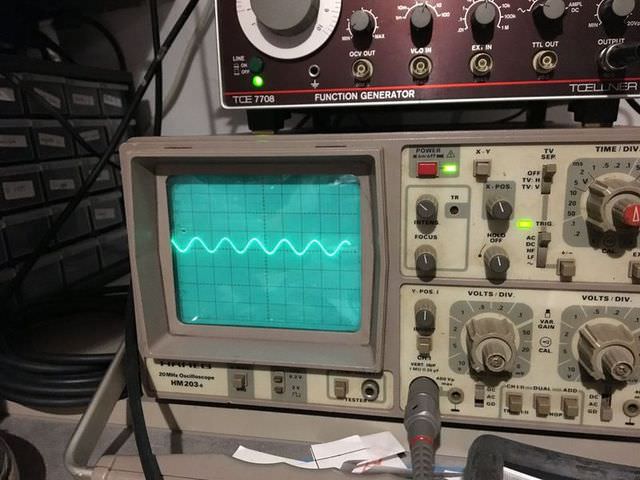
That's the regular input feeded where the capsule lands.
LBjzwla.jpg


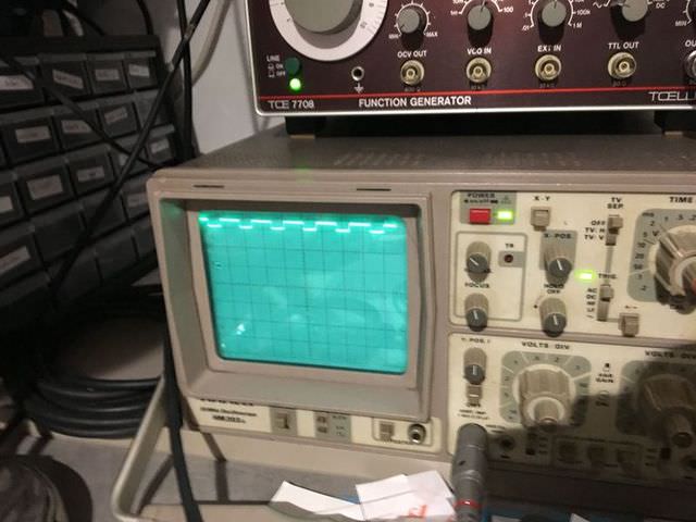
Here's the output.
yRkcosA.jpg


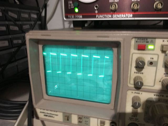
And this is what I got on B/BB
La4t8gs.jpg


I did re-heat everything and re-solder some suspicious pads. I also checked C1, C2, C3, R2 (although I just can guess it's more than 20M) and replaced T2. Voltages seem fine, considering that I only got 44v from the phantom.
I'm quite lost actually.  :-\
 
Did you follow the proper instruction for the 200 or 220m resistor in No R+ pad ?
this is a common mistake ,
hope this helps,
best,
Dan,
 
Thank for replying.

Well I think I did. :(

BKa2Im1.jpg


As I can't directly test the 200M, I did run a parrallel test for the 2 (200+20) of them. I got a perfect 18.18M, so both are ok.
 
I'v just finished to build the board.
i have some trouble with it.

I have a reallly reallly  tinny  output level. but it seemed to be a clean signal (my voice for test). But with or without the 48V i have the same little output signal.

i'v checked everythin Twice. The cinemag is wired as the pictures. The 220M resistor is at the right place. the  jumper instead of the pot and the 6.8r at r6 too. where can i start to trouble shoot?
 
and for putting the tranny in place i printed this thing :
IMG_1053.JPG

https://www.dropbox.com/s/3dzygeizf10lp91/IMG_1053.JPG?dl=0

and here is the STL file if you want to print it too :

https://www.dropbox.com/s/clsqunge1x123hf/circuit%20adaptation%20U47FET%20V4.stl?dl=0
 
Hello,

I am working on the D-47Fet. I am having some trouble figuring out where the back diaphragm is placed, I might just be missing it but i can't seem to find it on the schematic. I am also confused about the FD. the schematic seems to say something other then the build thread.

I would be very appreciative of any feedback.

Cheers
D
 
Hi,
There is no back diaphragm used in a u47fet, this is a cardioid (supercardioid in fact) mic only, D47 fet is the same.
If you use a dual diaphragm capsule just leave the back diaphragm unconnected (you can use a sleeve of heatshrink to cover the end of cable).
For the front diaphragm just follow the build guide, it is right and follow the original schematic.
 
Hi there,
As I wasn’t able to find out what went wrong, I started to build a new one.
I did check everything twice, ´ve been very carefull : same shit.
Now, I am an unhappy owner of two non-working pieces of crap.
What a waste of time.  :'(


Attachments

  • 7403ADE4-D3EF-49B2-8E76-9974342186C9.jpeg
    7403ADE4-D3EF-49B2-8E76-9974342186C9.jpeg
    948.6 KB
You missed r16 the 10M resistor.
And please check your floating connection with the 1g resistor and so on. This seams not right to me.
Where are you living ?
Also take some isopropanol and clean.
Be careful with the styroflex.
 
Boomfred,

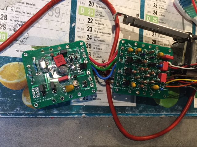
Correct me if I'm wrong but from the pictures of your bench, it looks like you're injecting a large signal.  If you're using a simple capacitor to simulate the capsule, the signal is very small, in the order of milivolts.  You're output may just be clipping.  What is the level you're injecting and what is the voltage you read?

Regards,
Jeff
 

Latest posts

Back
Top