solarplexus
Member
- Joined
- Sep 10, 2012
- Messages
- 14
Hi, I am wondering which one of the capsules are best for this project? The Peluso or the Microphone Parts? Quite a bit difference in price... is there quite a bit difference in quality?
I received the switches today. I will test them in a few hours to know if there's nothing wrong with audio but size is a lot better IMOlolo-m said:DUDE GUY said:Hello,
I'm trying to source the pattern and pad/filter switches for poctop or chunger's switch pcbs and I found these switches on mouser. Can anyone tell me:
Will this work as the pattern switch?
http://www.mouser.com/ProductDetail/CK-Components/ET03SD1ABE/?qs=sGAEpiMZZMtn8lxF5bBjIQWcN3oQfoXv
Will this work as the pad/filter switch?
http://www.mouser.com/ProductDetail/CK-Components/ET01MD1ABE/?qs=sGAEpiMZZMuIC3ROaEqRYe45DaHRdpBu
Thanks,
-Kevin
First of all Chunger is selling his donnor bodys with switches. The only thing you can regret is the length of the actuator part. The switches are too long IMO and even if they are a lot more easy to activate I don't like very much the aesthetic of those actuators getting to much out of the body.
As I am going to make an order to Mouser I will try those ones that should fit perfectly and I will tell you if they does or not :
patern : http://fr.mouser.com/ProductDetail/CK-Components/ET03MD1ABE/?qs=sGAEpiMZZMvudeGI7i40XCtw4Fd8ZUmCnC%252blw%2fFanIU%3d
pad / filter: http://fr.mouser.com/ProductDetail/CK-Components/ET01MD1AGE/?qs=sGAEpiMZZMvudeGI7i40XCtw4Fd8ZUmCSL%252bogZhXbYQ%3d
They are meant to work under 20v but we don't have any power there so I think they should be OK. If someone doesn't agree feel free to post about this. Thanks !
solarplexus said:Hi, I am wondering which one of the capsules are best for this project? The Peluso or the Microphone Parts? Quite a bit difference in price... is there quite a bit difference in quality?
neonwitch said:Hello,
I am working on version 1.2 of this PCB. I noted that there are 3 solder pads for R11. Does leg 3 still need to be clipped off and leg 2 bent to fit into solder pad 3? There does not appear to be a trace going to solder pad 3.
I am biasing using my DAW oscilloscope. Changing the value of R11 does not appear to have any effect on the sine wave or the sound of the tone. The potentiometer at r11 is functioning normally according to my DMM. The sine wave is distorted and of low amplitude when the probe grounds are attached to the mic ground rails, and normal when the probe grounds are lifted.
When I was trying to determine JFET IDss, I shorted the wrong two legs together when hooking them up to a 9v battery. Would this have fried the FET by biasing it in the wrong direction? Also, when I was soldering a component, I accidentley let the soldering iron rest on the transistor for approx. 3 seconds. It seems that the first place I need to look for a fault is the FET. Based on this information, would you agree?
Any help would be greatly appreciated.
Thanks,
Greg.
poctop said:the thing with biasing is that you have to have your mic output wired in order to supply the mic ciurcuit with the phantom power ( 48V) if not then the circuit is not powered onLet me know if this helps,
Dan,
kjdemarest123 said:How do I wire the patterns on my PCB if my mic only has two options, an omni and hypercard (no figure 8)?
Also, my capsule only has three wires: FC, BC, and a body wire. Which label should I solder the body wire to?
kjdemarest123 said:How do I wire the patterns on my PCB if my mic only has two options, an omni and hypercard (no figure 8)?
Also, my capsule only has three wires: FC, BC, and a body wire. Which label should I solder the body wire to?


ramshackles said:Hi,
I've finished my u87 and it seems to work well except that I get loud pops when I flick the switches.
I'm guessing I have some kind of grounding problem, or perhaps a general wiring problem?
I just used bits of bread board to attach the switches to the body..perhaps that isn't the way to go (Chunger seemed to have a nice switch PCB on his build thread...that available anywhere?)
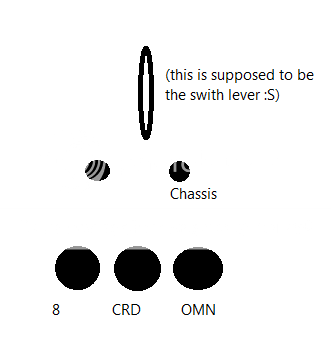
Here is how I wired the pattern select switch, looking at it from the bottom:

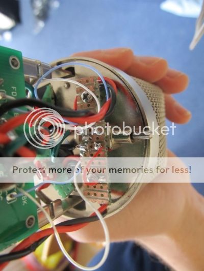
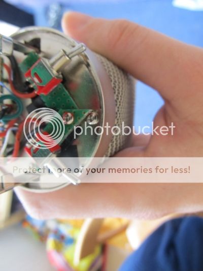
Here are some shots of the switches:


neonwitch said:Hello,
I biased the FET using the listening method and was able to find the sweet spot fairly easily. I measured 11.5v at the FET drain after I had found this spot. The mic does pass signal, but is very noisy with random popping. Turning on the pad or high pass has no effect on the pops. If I tweak R11 past the sweet spot so that I measure >26v at the drain, the pops disappear. The noise floor is still very high though. Also, when the drain voltage is set to 11.5v, I only have 11v at the zener. When R11 is set too high, the zener voltage is correct. I have cleaned both sides of the board with isopropyl alcohol and toothbrush. I did not use styrene caps for this build. Is the transistor shot, or is there a problem with one of the components?
thanks,
greg