You are using an out of date browser. It may not display this or other websites correctly.
You should upgrade or use an alternative browser.
You should upgrade or use an alternative browser.
Neumann Vintage U87 Clone : Build Thread.
- Thread starter poctop
- Start date
Help Support GroupDIY Audio Forum:
This site may earn a commission from merchant affiliate
links, including eBay, Amazon, and others.
kante1603
Well-known member
Hello,
@jasonallenh,
you don't need the jumpers when using switches.Just solder the leads to their corresponding jumper connections.Pad and hpf are easy,whether the switch is open condition meaning not active or closed which will activate the function.You can ohm the switches out and then know which direction the switch knobs must show.
For the pattern switch,a center-off is exactly what you need!
Please look at my pdf in reply 189 on page 10,this should clear it up.
Remember that center position on the switch is the open condition,therefore it will be your cardioid pattern.You might have to re-label the writing on the mic housing.
@Andrew:
Can you send a pic of your transformer please?
Looks like the sticker is only reversed,there's no bottom or top,just primaries and secondaries.
The pair with the readings around 21ohm go to the xlr side.
To check phase you can do as follows:
Hook up the u87 and another known mic to two mixer or daw channels in front of the same signal source,e.g. your voice.Same distance for both.Set the gains so both match to equal level on your meters.
Pan for both to midle position.
Now listen to both at the same time meanig the summed up signal.
Flip the phase on one channel,doesn't matter which one.
You should now have a lower level and thinner sounding signal.
If that's the case you're done.If not just reverse the two leads that go to the xlr side.Done.
.....and don't do that 9v battery thing..........
Hope to have helped,
Best,
Udo.
wink0195
Member
- Joined
- Jun 4, 2012
- Messages
- 21
Here is a pic of the ami t13 transformer. When my multimeter is attached to the yellow leads (via 2 probes) it reads 21R and when testing the black leads it reads 436R so i suspect my t13 is one of the reversed...
http://i1218.photobucket.com/albums/dd419/Andrew_Winkler/IMG_2599.jpg
http://i1218.photobucket.com/albums/dd419/Andrew_Winkler/IMG_2599.jpg
jasonallenh
Well-known member
kante1603 said:You might have to re-label the writing on the mic housing.
Not if I have anything to do with it! I'm running wire directly from the switch to the switch points on the PCB. I cut all the leads on the original switch PCB so it only serves to hold the switches in place, therefore i can wire the switch to match the labelling ;D
Now I can start my next step. I haven't had pictures in a while because i've been bogged down in other projects, but I'm not giving up on this!
kante1603
Well-known member
Yes,so the yellow leads go to xlr side.wink0195 said:Here is a pic of the ami t13 transformer. When my multimeter is attached to the yellow leads (via 2 probes) it reads 21R and when testing the black leads it reads 436R so i suspect my t13 is one of the reversed...
http://i1218.photobucket.com/albums/dd419/Andrew_Winkler/IMG_2599.jpg
To keep them in phase simply remember which side they are coming off the transformer,these black & yellow "pairs" belong together phase- wise.Cool.
Best,
Udo.
kante1603
Well-known member
No,you can't because the only open condition is the middle switch position,at least it was on all B2 builds I know of.jasonallenh said:kante1603 said:You might have to re-label the writing on the mic housing.
Not if I have anything to do with it! I'm running wire directly from the switch to the switch points on the PCB. I cut all the leads on the original switch PCB so it only serves to hold the switches in place, therefore i can wire the switch to match the labelling ;D
Or is your original labeling cardioid in the middle?If so then we have another B2 version here.
If not then relabeling is necessary.You cannot swap the wires as you need them,refer to the schematic and my before-mentioned pdf.This explains why.
Best,
Udo.
wink0195
Member
- Joined
- Jun 4, 2012
- Messages
- 21
jasonallenh
Well-known member
kante1603 said:No,you can't because the only open condition is the middle switch position,at least it was on all B2 builds I know of.jasonallenh said:kante1603 said:You might have to re-label the writing on the mic housing.
Not if I have anything to do with it! I'm running wire directly from the switch to the switch points on the PCB. I cut all the leads on the original switch PCB so it only serves to hold the switches in place, therefore i can wire the switch to match the labelling ;D
Or is your original labeling cardioid in the middle?If so then we have another B2 version here.
If not then relabeling is necessary.You cannot swap the wires as you need them,refer to the schematic and my before-mentioned pdf.This explains why.
Best,
Udo.
WHOOOOOPS, yea, i didn't even think about that. I just assumed that outside labels were flipped, not completely out of order. you're totally right.
wink0195 said:
I didn't bother with this step.... for 1, I didn't want to have anything to do with the PCB (it's super cheap... I've self etched better PCBS in a rubbermaid tub), and second, they have pins of some switches shorted together (i guess for their own circuitry, which scks anyway).
So what I'm doing is this-
I cut every single PCB lead except for the ground/shield
then solder some thin two and three lead ribbon cables directly onto the switch leads.
I'll drill some small holes through the crappy plastic center part to run some wires direct to the switch points on the PCB.
The bhrngr PCB has little jumper wires, and other junk that made no sense to me so i got rid of all of it. It only serves a structural purpose for me.
wink0195
Member
- Joined
- Jun 4, 2012
- Messages
- 21
jasonallenh said:So what I'm doing is this-
I cut every single PCB lead except for the ground/shield
then solder some thin two and three lead ribbon cables directly onto the switch leads.
I'll drill some small holes through the crappy plastic center part to run some wires direct to the switch points on the PCB.
The bhrngr PCB has little jumper wires, and other junk that made no sense to me so i got rid of all of it. It only serves a structural purpose for me.
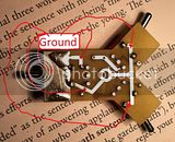
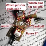
Ok, I can for sure cut all the leads and solder directly to the switch pins, but which pins on the switches do I attach the 2 - 3 pin ribbon cables to so that they match up with the indicated patterns? and how do they coordinate with the pcb?
I labeled the pins "1,2, and 3" so you could easily explain via message where i should solder the ribbon leads, however, "PAD" and "LC" on the PCB aren't labled "in" and "out" either so plz just refer to them as "Pad PCB left" and "Pad PCB right" in coordination to looking at the silkscreen labels side of the pcb. do you follow me?
Also did I cut all the appropriate leads? I don't wanna short out my back plate :'(
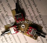
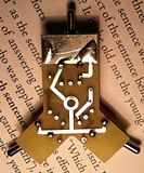
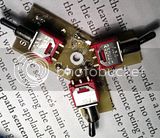
(Click on thumbnails to enlarge and view properly)
kante1603
Well-known member
@jasonallenh
Hi,
Let us know how it worked out and show some pics please.
Best regards,
Udo.
Hi,
I know....... ;Djasonallenh said:WHOOOOOPS, yea, i didn't even think about that. I just assumed that outside labels were flipped, not completely out of order. you're totally right.
O.K.jasonallenh said:I didn't bother with this step.... for 1, I didn't want to have anything to do with the PCB (it's super cheap... I've self etched better PCBS in a rubbermaid tub), and second, they have pins of some switches shorted together (i guess for their own circuitry, which scks anyway).
Correct,and you can use any thin wire,no high current here.jasonallenh said:So what I'm doing is this-
I cut every single PCB lead except for the ground/shield
then solder some thin two and three lead ribbon cables directly onto the switch leads.
I'll drill some small holes through the crappy plastic center part to run some wires direct to the switch points on the PCB.
The bhrngr PCB has little jumper wires, and other junk that made no sense to me so i got rid of all of it. It only serves a structural purpose for me.
Let us know how it worked out and show some pics please.
Best regards,
Udo.
kante1603
Well-known member
@wink0195
Hi Andrew,
One thing that is imperative here:Since I don´t know how this board is mounted inside your mic it is best to run a wire from the board ground to a good point on the pcb or the mounting rails.The switch board ground connections are connected to their metall plates surrounding the switches.These are meant as shields.If not done properly the switch knobs themselves act as an "antenna" and can pick up rf-noise.When touched you would get an ugly hum too.Quite a few guys here did this wrong from what I remember.
The big ground pad on the left (on the switch board) will serve you well.
But don´t worry,it´s an easy one!
All the what you named "pin 2" connections are used.For the HPF and the pad it doesn´t matter to which of the dual connection on the main pcb they go to.But the pin 2 of the pattern switch must go to the middle connection of the triple pad on the main pcb!
Next step is to figure out which pins (1 or 3) goes where,it´s easy again:
When looking at the labels and where the knob tips show to-it´s always the oposite outer pin that refers to it!
Think toggle switches acting like a "seesaw"(hope that is the correct english word?).
An example:The switch knob tip shows to the left means the middle pin and the outer right pin are connected (ohm that out if you want).Same on the other side,tip shows to the right means middle pin connects to the outer left pin.That´s it!
The only difference is the pattern switch that has a middle position.In this case the pin 2 simply connects to nowhere.
So for the HPF and the pad one side of the switch is unconnected,the pattern switch uses all 3 connections.
Have found a nice additional explaination on how switches work,see the second drawing:
http://www.musicfromouterspace.com/analogsynth_new/ELECTRONICS/pdf/switches_demystified_assembly.pdf
Hope it´s all clear now,you´re getting pretty close to it!
Best,
Udo
Hi Andrew,
O.K. so far,but you must cut the trace ground to the left (pattern?) switch too.Can be done with a sharp knife,it´s easy.wink0195 said:Ok, I can for sure cut all the leads and solder directly to the switch pins, but which pins on the switches do I attach the 2 - 3 pin ribbon cables to so that they match up with the indicated patterns? and how do they coordinate with the pcb?
I labeled the pins "1,2, and 3" so you could easily explain via message where i should solder the ribbon leads, however, "PAD" and "LC" on the PCB aren't labled "in" and "out" either so plz just refer to them as "Pad PCB left" and "Pad PCB right" in coordination to looking at the silkscreen labels side of the pcb. do you follow me?
Also did I cut all the appropriate leads? I don't wanna short out my back plate :'(
(Click on thumbnails to enlarge and view properly)

One thing that is imperative here:Since I don´t know how this board is mounted inside your mic it is best to run a wire from the board ground to a good point on the pcb or the mounting rails.The switch board ground connections are connected to their metall plates surrounding the switches.These are meant as shields.If not done properly the switch knobs themselves act as an "antenna" and can pick up rf-noise.When touched you would get an ugly hum too.Quite a few guys here did this wrong from what I remember.
The big ground pad on the left (on the switch board) will serve you well.
As said I don´t know which side show upwards or downwards nor do I know how your housing s labelled.wink0195 said:
But don´t worry,it´s an easy one!
All the what you named "pin 2" connections are used.For the HPF and the pad it doesn´t matter to which of the dual connection on the main pcb they go to.But the pin 2 of the pattern switch must go to the middle connection of the triple pad on the main pcb!
Next step is to figure out which pins (1 or 3) goes where,it´s easy again:
When looking at the labels and where the knob tips show to-it´s always the oposite outer pin that refers to it!
Think toggle switches acting like a "seesaw"(hope that is the correct english word?).
An example:The switch knob tip shows to the left means the middle pin and the outer right pin are connected (ohm that out if you want).Same on the other side,tip shows to the right means middle pin connects to the outer left pin.That´s it!
The only difference is the pattern switch that has a middle position.In this case the pin 2 simply connects to nowhere.
So for the HPF and the pad one side of the switch is unconnected,the pattern switch uses all 3 connections.
Have found a nice additional explaination on how switches work,see the second drawing:
http://www.musicfromouterspace.com/analogsynth_new/ELECTRONICS/pdf/switches_demystified_assembly.pdf
Hope it´s all clear now,you´re getting pretty close to it!
Best,
Udo
kante1603
Well-known member
Bitteschön! ;Dwink0195 said:Vielen dank Udo. Ich würde ohne deine Hilfe verloren. Ich werde viele Fotos
JessJackson
Well-known member
First recording i used my u87 on
http://www.youtube.com/watch?v=MzVdDHpSuNc&feature=share&list=UU-Eh1lR_tWVtv9AvxLybMtQ
Had to De ess a lot, top end needs taming, don't expect to hear unprocessed recording from me. lol
J
http://www.youtube.com/watch?v=MzVdDHpSuNc&feature=share&list=UU-Eh1lR_tWVtv9AvxLybMtQ
Had to De ess a lot, top end needs taming, don't expect to hear unprocessed recording from me. lol
J
kante1603
Well-known member
Hi Jess,JessJackson said:First recording i used my u87 on
http://www.youtube.com/watch?v=MzVdDHpSuNc&feature=share&list=UU-Eh1lR_tWVtv9AvxLybMtQ
Had to De ess a lot, top end needs taming, don't expect to hear unprocessed recording from me. lol
J
can you post a pure untreated track of the vox please?It's impossible at least for me to comment on the mic sound,it is way to sharp for my ears this way.When you say you even had to de-ess a lot then I would start thinking there's something not so propper as it should be.Can you tell us a bit more on your mic about which capsule you used and if you went for styrenes,transformer choice etc.?
That would be useful.
Personally I can't remember to ever have had a de-esser on a U87 in the past 26 years during vocal tracking.
Just curious,
Udo.
Gonna have to agree with udo. Im using the peluso capsule with the AMI transformer and poly caps, there should be almost no need for de-essing on this mic unless someone is imitating a snake.
Pip
Well-known member
JessJackson said:First recording i used my u87 on
http://www.youtube.com/watch?v=MzVdDHpSuNc&feature=share&list=UU-Eh1lR_tWVtv9AvxLybMtQ
Had to De ess a lot, top end needs taming, don't expect to hear unprocessed recording from me. lol
J
Lots of stuff on that track my man. Vocal performance sounds good. Track sounds good. But as an engineer I can not comment on a mixed multitrack recording I must hear the raw track. A lot of Desssing can be brought on by a lot of issues. Singer, Mic position, humidity, EQing and the dreaded over compression.
kante1603
Well-known member
Hi Andrew,
The pads named SW and RT are the short form for the german words Schwarz (=Black) and Rot (=Red) and have been the original signal injection points by Neumann.You can omit them,they're not needed for "our" biasing method.
GLINK is GroundLink,an additional grounding point.Sometimes useful when it comes to grounding issues like that with the switches picking up noise.One of several points to run a wire to then,not needed when everything is good.
What's that unbalanced but phantom powered preamp,do you have a link or pic?
Best,
Udo.
Similar threads
- Replies
- 26
- Views
- 2K
- Replies
- 98
- Views
- 15K
- Replies
- 6
- Views
- 2K


![Soldering Iron Kit, 120W LED Digital Advanced Solder Iron Soldering Gun kit, 110V Welding Tools, Smart Temperature Control [356℉-932℉], Extra 5pcs Tips, Auto Sleep, Temp Calibration, Orange](https://m.media-amazon.com/images/I/51sFKu9SdeL._SL500_.jpg)


