Neve 1290 build completed!!

GroupDIY Audio Forum

Help Support GroupDIY Audio Forum:

This site may earn a commission from merchant affiliate links, including eBay, Amazon, and others.
Yea okay cool. I just decided to go back to my original idea and use the JLM Go Between, going to make things a lot easier and I'll also get a pad out of it. I'm sure I'll have more questions as I go along as this is my first real DIY.

Btw Jorge, you're 1290 build is very nice!
 
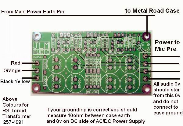
Sorry another question; this time about the Go Between. I'm pretty sure this is how the wiring works, can someone look this over and confirm.

gobetween-wiring.jpg


Also, for the +48, +24 and 0V I'm using 24 gauge stranded wire, is that enough?
 
Check here for all of the info: http://www.groupdiy.com/index.php?topic=22828

You'll just need to send madriaanse an email about the PCBs.
 
Hi Mandriaanse,
Would you have any spare PCB board left of your 16 you made ?
If not, would you have a vectorial drawing to manufacture them ?
Maybe we could share the cost of a bunch of them to be done for those interested ?
Thanks a lot.
Alex
 
Hi,

I am having it seems a louder than normal hiss and I was wondering if some can look at this pic to see if I can do something to quiet it down...........

Thanks
 

Attachments

  • SSPX0089.jpg
    SSPX0089.jpg
    157.3 KB
Ok thanks i will double check all caps and no I did not calibrate.... I read thru the manual but wasent sure on were to hook up my osciilloscope probe to adjust the trimmer if that is what u are refering to.  Also what do u mean leave out 0v at the outputs............

Thx
 
zachs said:
Sorry another question; this time about the Go Between. I'm pretty sure this is how the wiring works, can someone look this over and confirm.

gobetween-wiring.jpg


Also, for the +48, +24 and 0V I'm using 24 gauge stranded wire, is that enough?

Should 0volts from the PSU be connected also to the 0volts on the JLM go between?
 
madriaanse said:
Hi 3nity,

Like all 1073/1290's, these preamps have some hiss ("Neve haze"). They are not dead quiet, but the hiss shouldn't be distracting unless you're recording quiet sources with ribbon mics. The noise floor specs can be improved somewhat by hand-picking BC184C's for highest HFE (especially the first one in the darlington config), but I never bother.

HTH,

M.

I'm really sorry for this question,
but could someone tell me which is the first transistor in the Darlington config?

is it the one I marked on this picture?


Attachments

  • 1290 - darlington config question.JPG
    1290 - darlington config question.JPG
    69.5 KB
Blue is 1st stage, yellow 2nd...and black, driver stage.
 

Attachments

  • 1290_-_darlington_config_question[1].jpg
    1290_-_darlington_config_question[1].jpg
    167.5 KB
Hi Desol and Whoops,

You are both correct :)

TR2 on this PDF is the first in the Darlington pair:
http://www.musiciansgig.com/ez1290/transistor_voltages.pdf

K-Los:
To calibrate you can hook up the oscilloscope to the "line output" (after LO1166). So pin 2 goes to the tip of the probe and pin 3 to the ground clip on the probe.

Best,

M.
 
Thanks Madriaanse,

I choose the higher HFE transistors for those positions,and all the other ones I used have an HFE higher than 600.

I finished soldering all the wires in my 2 1290 pres,  tested it but there's only horrible noisy and crackles coming out of it.
It happens the same with both channels, so probably it was some mistake I did to both channels.

Going to try now, to figure out what's going on.
 
Hi Martin,

I've run into a problem with my EZ1290s that have been working fine until I took a break from using them for a while (several months) and just recently turned them back on. I have a two-channel 1RU that I've built. Both channels worked fine before, but now channel 1 is not working at all. I've traced the signal with the scope and it seems that the problem is in the driver stage around TR1/TR2 area. I've replaced both TR1 and TR2, as well as 2N3055 along with all of the caps in the driver stage - nothing has changed.

Then I found your Transistor Voltages PDF and measured some weird numbers at TR1 and TR2 (all of the voltages at 1st and 2nd preamp stages on BOTH channels are within normal figures):

On the broken channel I get (before and after replacing parts, as I mentioned above):

TR1 Collector: +1V, Base: -0.235V, Emitter: 0V (!)
TR2 Collector: +0.6V, Base: +1V, Emitter: +0.45V

Then I measured the channel that works (channel 2) but 2N3055 gets very hot (I would think hotter than it should):

TR1 Collector (as well as TR2 Base) measured +7.3V, as opposed to your suggested +3.6V - almost the double... The rest of the voltages in that area seem close to normal. Sonically channel 2 sounds OK though, while channel 1 is not outputting anything audible (just tiny hiss, meaning it is powered on) and 2N3055 on it is cold to touch as if the channel was fully off.

Not knowing the circuit well I'm currently lost as far as how to proceed... If you (or anyone else) have any suggestions I would greatly appreciate them! =)

Thanks!
 
Hi Promixe,

Strange problems you're having. What are you using for PSU and what are your rails at?

I'd start with the following:

make sure R3, R7, RV1 aren't cooked (68K, 47R, 5K trimpot)
swap out the 82uF's
make sure the TR3 collector has good continuity to the TR2 collector AND the output transformer. (make sure screws are tight).

Hope you have a good desoldering gun!!

M.

 
madriaanse said:
What are you using for PSU and what are your rails at?

I'm using FiveFish PSU2448 and my rail is at +24.04 (+\-0.02)

make sure the TR3 collector has good continuity to the TR2 collector AND the output transformer. (make sure screws are tight).

THAT FIXED channel 1! =) Pretty amazing... However TR1 Collector voltage is jumping up and down now... It is around +7.3V still now on BOTH channels (TR3 getting pretty toasty), but on channel 2 it is jumping between +7.2-7.4V, while on channel 1 (newly resurrected with a screwdriver) it is steady at +7.31V. I haven't listened to the "jumping" on channel 2, but looking at FFT (and scope) the whole spectrum jumps up and down, looking like it is crackling...

...I don't know what I just did but channel 2 TR1 Collector is at steady +7.26V now... Weird... I will research more and report...

Also, the LM317 on the PSU is getting VERY toasty. It makes me wonder if somehow it's pulling more current into the boards than it should...

Thanks a lot Martin!
 
Back
Top