Neve 1290 build completed!!

GroupDIY Audio Forum

Help Support GroupDIY Audio Forum:

This site may earn a commission from merchant affiliate links, including eBay, Amazon, and others.
Your board is probably oscillating. If you look back a few pages, stitch-o solved his oscillation problem by tying the board to the chassis using the mounting hole near the 5K trimmer. You could do this by replacing the plastic standoff with a screw and a few nuts. Before you drill a hole though, you could test this by soldering from the PCB hole between the input trafo pads and the power pads and tying it to the chassis. (Just check that this is connected to the PCB ground trace cuz I have a previous version of the board). You may also want to put that 10R 1W resistor in series here.
 
ok thanks mitsos i will give that a go. i did read stich-o's post before but didnt think my problem was the same as my audio just completly dies rather than crackles. Plus my right board is fine.
 
gerardmanvuca said:
ok thanks mitsos i will give that a go. i did read stich-o's post before but didnt think my problem was the same as my audio just completly dies rather than crackles. Plus my right board is fine.
Oscillation would cause the audio to drop out. IIRC in stitch's case, the audio would drop out in the last few gain spots. This was fixed by grounding the board, but the crackle was not. His crackle problem is (probably) something else.

The odd thing is that you have one channel working and one not... yet they are both on those plastic stand-offs.
 
gerardmanvuca said:
haha building a guitar next 2 ur bed. thats crazy dude hehe. The toroid is from RS. Its in the euro bom. It was 20 quid cheaper than digikey!!  i got most parts frm digikey apart from the toroid, PSU case, xlr connectors, and some odd caps here and there that digikey had out of stock. i got all those from RS.  ................
Hi gerardmanvuca
have you a link about "1290" euro bom ?
thanks
6t9r
 
mitsos said:
Oscillation would cause the audio to drop out. IIRC in stitch's case, the audio would drop out in the last few gain spots. This was fixed by grounding the board, but the crackle was not. His crackle problem is (probably) something else.

Poor solder points to the input transformers!
I had that freakin crackle creep back in and out, but only in the left channel after I rewired the right channels input transformer.
As per Martin's suggestion, I went back in and resoldered the main pins to the input trunny and BINGO!
Crackle free, Neve-y goodness.
Fried the 48V rail building a stupid voltage divider network to power a front panel LED so I ordered a nice green 28V panel mount and will tie it into the 24V/0V at the 4pin XLR. A 1N4007 in series with the anode just in case.

Grounding that standoff to case was a great thing. Oscillation problem fixed.

Checking voltages is a great thing, especially if you have a channel that isn't passing anything at all...
That can help you focus in on the problem and where in the circuit it is. Usually (9 times out of 10) it is something very small and easy.
 
stitch-o said:
Poor solder points to the input transformers!
I had that freakin crackle creep back in and out, but only in the left channel after I rewired the right channels input transformer.
As per Martin's suggestion, I went back in and resoldered the main pins to the input trunny and BINGO!
Crackle free, Neve-y goodness.
F

So my suspicions were right all along!!!

I still get my crackle but havent had time to look at it again yet.

Good to know there is a definite answer though.

Cheers
Jake
 
snipsnip said:
stitch-o said:
Poor solder points to the input transformers!
I had that freakin crackle creep back in and out, but only in the left channel after I rewired the right channels input transformer.
As per Martin's suggestion, I went back in and resoldered the main pins to the input trunny and BINGO!
Crackle free, Neve-y goodness.
F

So my suspicions were right all along!!!

I still get my crackle but havent had time to look at it again yet.

Good to know there is a definite answer though.

Cheers
Jake

Yesyes!

Thanks again for your good advice, Jake.

Cheers!
 
SIXTYNINER said:
gerardmanvuca said:
haha building a guitar next 2 ur bed. thats crazy dude hehe. The toroid is from RS. Its in the euro bom. It was 20 quid cheaper than digikey!!  i got most parts frm digikey apart from the toroid, PSU case, xlr connectors, and some odd caps here and there that digikey had out of stock. i got all those from RS.  ................
Hi gerardmanvuca
have you a link about "1290" euro bom ?
thanks
6t9r
i cant remember where the hell i found it but its round this thread sumwhere!??!  so i just uploaded the jpegs (they were jpeg where i downloaded them from) to my photobucket account......here u go:

http://i282.photobucket.com/albums/kk280/iamproof/3118994469_3441f0954b_b.jpg

and

http://i282.photobucket.com/albums/kk280/iamproof/3119124401_1bdd7f7ff0_b.jpg


Also i aint had time to ground my board yet...guna do that in the next cuple of hours and report back.

1 other thing....on the JLM site they say to only use the 0V from the ac/dc for audio 0v. They say to use the mains ground for all chassis grounding! but i see lots of peeps here (incl madriaanse) using the ac/dc 0v for chassis grounding???? cud someone enlighten me on this........many thanks, Gere
 
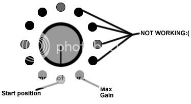
Ok tried grounding the hole by the trimer like u guys said but didn't make any diffrence :'(. still no audio on these steps:
notworkin.jpg


But the right channel is fine??!  weird cus i soldered these 2 boards up at the same time and kept them pretty consistant.....i'm wonderin if i mite of burnt out some of the resistors by the knob as i started the soldering process with these...and i was a bit rusty to begin with...got into my groove after the resistors.

u mentioned i should trace the audio....sorry i'm a bit at a loss on how to do that...could someone give me a quick description on how to do that? wud be well appreciated, Cheers Gerard.

P.s i did check tr voltages and they're pretty spot on compared to madrianse's chart.  plus they are the same accross both boards. and since the right channel is working wud that mean the problem doesnt lie with the transistors? sorry i'm a bit of a newb ::)
 
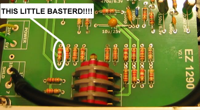
ok ALL IS GOOD! figured out the problem.....i was measuring resistor values across both boards and found that there was a discrepancy....the 3k9 on the broken board was reading 50.8K!? whilst on the working board it was a more respectable 3.6k...so i swapped it out with a new one (measured 3.6k on the board) and voila! all is workin great.......the weird thing is i re-measured the broken resistor now that its out the board and its reading 3.8k????weird but watever...like i care  8)
BASTERD.jpg
 
snipsnip said:
Thats good work as I didnt think you could effectivly measure resistors once they were in a circuit.

You can not measure them in circuit, you have to pull one leg of the resistor to measure.

BUT, if replacing the resistor worked, more power to ya!
Might have been a bad solder point....
FWIW: That resistor measuring 3.8k, more than likely, IS a 3.9k with a 5% tolerance.
 
stitch-o said:
You can not measure them in circuit, you have to pull one leg of the resistor to measure.

nothing personal to you, but i have been keep reading this comment on other pages too...
i have a fluke 187 and i can even measure capacitors accurately without pulling one leg off...
i have done many tests for it...
i have to switch the power off tho... if resistor or cap in parallel with an other, i read paralleled value, naturally...

only in some specific situations i cant read accurately, but thats been very very rare so far...
i only pull one leg off, if i read strange values... i have been doing well with this system...
it may not be appropriate for low budget DMMs... i have no idea why i read spot on values  ::)

 
gerardmanvuca said:
ok ALL IS GOOD! figured out the problem.....i was measuring resistor values across both boards and found that there was a discrepancy....the 3k9 on the broken board was reading 50.8K!?

Hats off to you sir!! Nice work!!

1 other thing....on the JLM site they say to only use the 0V from the ac/dc for audio 0v. They say to use the mains ground for all chassis grounding! but i see lots of peeps here (incl madriaanse) using the ac/dc 0v for chassis grounding?Huh cud someone enlighten me on this........many thanks, Gere

I need to clarify this better:

-I use the ACDC's earth connection point (the top right mounting hole on the ACDC PCB) for chassis connection. So the following are all tied together inside the PSU box: Wall outlet ground, PSU chassis, ACDC earth connection point, pin 2 of 4pin XLR (I'll explain).

-The 2nd pin on the 4-pin XLR (shown as unused in assembly guide) is used to tie the chassis of the external PSU box to the mic pre's rack case. I use the drain wire in the shielded power cable for this. (I used shielded, 4 conductor, 18gauge)

-***0V is used for "audio ground" only.***

-Use plastic standoffs for the EZ1290 boards

-Doing it this way means there is 10 ohms resistance between earth/chassis and audio ground/0V.

-Connecting 0V to chassis can (and probably will) increase the likelyhood of interference and ground loops.

Hope this helps

M.
 
-Doing it this way means there is 10 ohms resistance between earth/chassis and audio ground/0V
how is the 10 Ohm resistance achieved?  I know there is a 10R 1W on the schemo, but where is this placed?
 
The 10R (along with a .1uF ceramic cap) is connected between 0V and earth on the ACDC PCB itself (top right corner). This is why you want to use the top right mounting hole to connect to chassis/earth.

M.
 
i have a question about the trim. if i instal the trim will it mean i can push the input gain more and therefore driving the circuit more to get a bit more warmth for colouring my mixes?
 

Latest posts

Back
Top