crisotop
Well-known member
yes, the cap was completely removed, with no change. I'll double check all components tomorrow, will report back any suspicious findings...
night,
christoph
night,
christoph


")
canidoit said:Onlymee, are there any common build errors that usually could lead to a non smooth and non performance optimized build? Like cap too close to this will cause oscillation or noise, etc.
Thanks

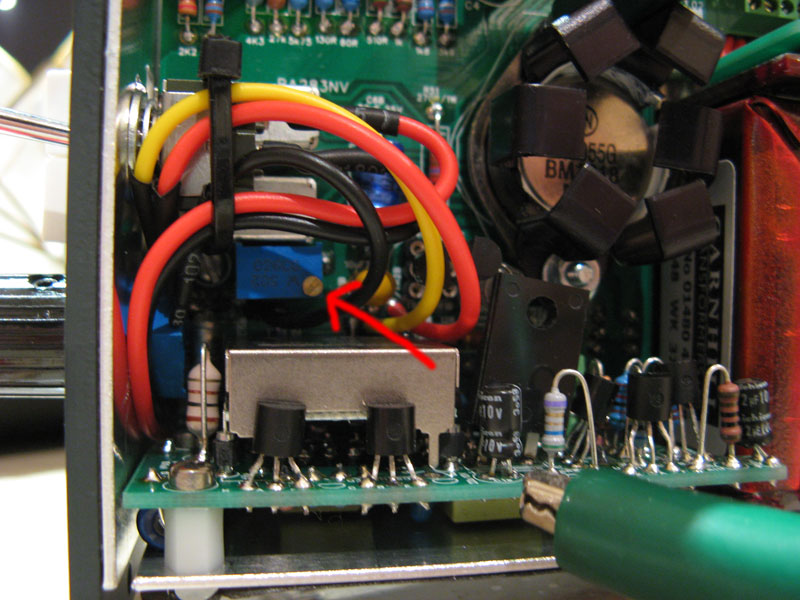
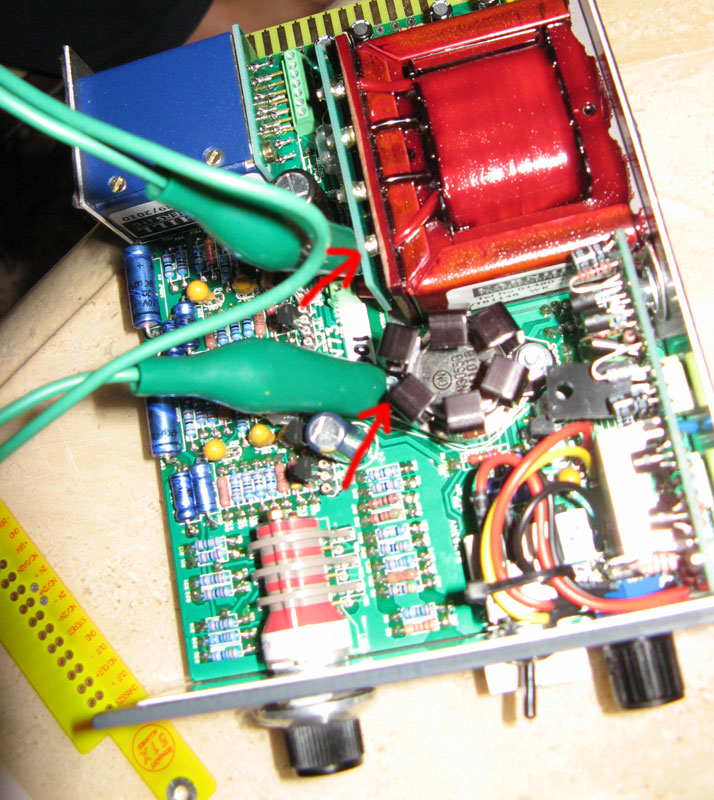
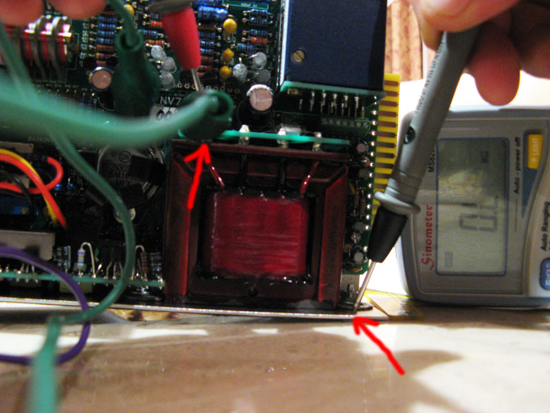
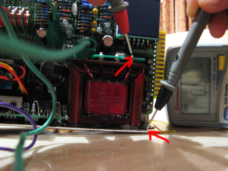
Onlymee thanks!onlymeeee said:Oh canidoit... you were asking about increasing gain before and if it wasn't stable what should you do... well I've troubleshooted it for you.. what you need to do is add a 100uF 35V capacitor - positive side straight on the output transformer pin 3 (+24V) and the negative end on pin 13 on the gold connector (ground). tested up to 75dB (no reason why 80dB wouldn't work too)
It shouldn't change the sound as it's just an extra cap on the +24V rail. (there's already 1000uF on there, but an extra 100uF right on the transformer pin seems to clear up any stability trouble) On a scope I don't see any changes on 65dB setting.
As it can be done without unscrewing anything it's very easy to mod. I've been adding it anyway for extra security as although without works perfectly fine in GDIY 51X or API lunchboxes, or my own hashed up test jig, one person was saying on a BAE rack, when unloaded and turned to max gain it oscillated. The cap solves this. Not sure why it would happen on BAE and not others ? Maybe the extra wiring instead the rack of PCB picks up like an little antenna(?) Speculation.
kishibashi said:Received my two boards today! Very cleverly laid out and lots of fun to solder. Ones completely soldered up and will finish the second one tomorrow. Now if only those trannys and switch would get here from AML...
Thanks for a great project! Can't wait to power them up and run them through their paces next to my vintage and reissue 1084's!
From what I understand, you do not install the whole DC-DC converter PCB but double check with onlymeee.andre tchmil said:I went through all 31 pages but couldn't find the answer nor in the Bom . Is the DC convertor the only part to leave out when running at 24v only ?
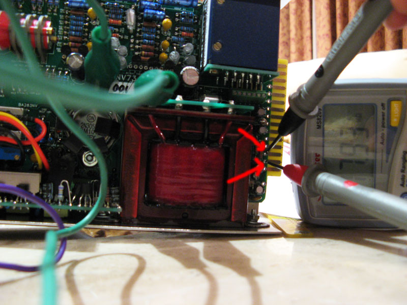
if it helpsonlymeeee said:Max current draw is around 123mA on turn on with +-16V.
24V rail is less but haven't got my numbers on it at hand...
Enter your email address to join:


![Electronics Soldering Iron Kit, [Upgraded] Soldering Iron 110V 90W LCD Digital Portable Soldering Kit 180-480℃(356-896℉), Welding Tool with ON/OFF Switch, Auto-sleep, Thermostatic Design](https://m.media-amazon.com/images/I/41gRDnlyfJS._SL500_.jpg)


