New GSSL Layout Proposal - Anyone Interested?

GroupDIY Audio Forum

Help Support GroupDIY Audio Forum:

This site may earn a commission from merchant affiliate links, including eBay, Amazon, and others.
I rather say thanks as first. This is the stuf I'm learning form, comparing schematics. Since my knowledge to electronics is limited, I'm very glad that guys from a much higher level like Igor share this kind of information. Muchos respectos
 
Igor said:
                                                                 Paths going to control ports of VCA's have
low impedances, and 30R or 36R (for example) switch resistanse (Ron) DOES matters as well
as theirs mismatch.

Depends where the switches are, of course. While I agree with your general point, for things like sidechains where the difference between 0.001% and 0.01% distortion is mostly irrelevant I sometimes add an extra non-inverting op-amp buffer to allow me to use (cheaper) FET-switches.

JDB.
 
Sure, for ratio switch, it is possible to use even 4066 etc at +/- 7.5V as there's no high signals as well as impedances are high. For audio, using FET switches is bad tone...
 
Hi Ruckus !

A new idea comes to me right now : what about a dry/wet knob to achieve parallel compression directly inside the box ?
 
Igor said:
In GSSL mode, sum after sidechain filters. It is stereo music signal.

I used Lorlin 2x6 on my 500 Mixbuzz.

Practically, when I did listening tests with first 1RU build (it was 3 years ago), I got to next decisions.
After summing the signals in GSSL mode,(-6db) I put this down for about 3db than used +6db amp
which works as buffer as well. This way, the threshold stays almost at same place when passing from
4000 to GSSL link, at real audio signal. This gives a same chance to both modes sound good.

Yea, but who cares about the fact that it's a stereo s/c if you're summing the s/c signal?  So after staring at it a little more, who cares if you sum it before or after the hpf?  As long as you adjust the gain staging accordingly wherever you do.  Unless I'm completely missing something here, if you put the switch before the filter, as long as you adjust your gain there via resistor values then you're fine.  (for dual ssc boards for example it's a 10K input resistor when in SSL mode, and 2 x 20K in GSSL mode).

SIDE NOTE:

As far as dual mono & wet/dry - won't be a feature on this version.  Too much involved and out of room on the front panel as it is with all of the other feature additions.  I've managed to cover damn near everything else though.  Honestly, I'm really proud of what I've come up with and I think you guys are gonna be QUITE happy.  And there's an extra surprise that's going to make life even easier with this thing.  Don't want to give away all of the details quite yet, but stay tuned, it will be unleashed soon.
 
ruckus328 said:
SIDE NOTE:

As far as dual mono & wet/dry - won't be a feature on this version.  Too much involved and out of room on the front panel as it is with all of the other feature additions.  I've managed to cover damn near everything else though.  Honestly, I'm really proud of what I've come up with and I think you guys are gonna be QUITE happy.  And there's an extra surprise that's going to make life even easier with this thing.  Don't want to give away all of the details quite yet, but stay tuned, it will be unleashed soon.

Oh man, now that i've stopped laughing my ass off.

I think you should be proud of what you've done Mike! Absolutely man. Keep on truckin...
All the SSL design's are nice. Were here to encourage each other. It's a small, special community we have here, i think.

I think, it's *manditory* to privately message someone first with any concerns before globally posting, to clear up any misunderstandings or false assumptions. We've all been guilty of it at one time or another, i'm sure.

Peace out brotha's,
Darrick

- back to topic :)
 
Yea, but who cares about the fact that it's a stereo s/c if you're summing the s/c signal?
It is a bit different. Especially on electronic music with "phased" bass. To get this or that kind of compression. Of course, nothing matters when something has to be simplified :)
As far as dual mono & wet/dry - won't be a feature on this version.  Too much involved and out of room on the front panel as it is with all of the other feature additions.  I've managed to cover damn near everything else though.  Honestly, I'm really proud of what I've come up with and I think you guys are gonna be QUITE happy.  And there's an extra surprise that's going to make life even easier with this thing.  Don't want to give away all of the details quite yet, but stay tuned, it will be unleashed soon.

C&B is great feature.
Just listened to very rough, preliminary design of m/s and c&b for my Mixbuzz.
I found both way useful, as well m/s balance control before and after the compressor.
I.e. definately there will be additional M/S and DRY/WET strip in 500 format which can be added to
existing compressor.
I took whole drum set, added reverb to snare and bit of reverb to OH's,
than, squashed it (I raised S signal before the compressor by approx. 4 db and 3 db after compressor),
than, compressed with fast settings signal (about 12-15 db GR) was added to clean.
The mix was about 25wet:75 dry.
The thing I hate is crispy punchy talks. In one word: F@ING SOUNDS GOOD!!!!
 
Yeah CnB rules. I'm just about to dip rev5 here into the tank and proto it.

What's your take on the operating principle apart from the one we have here, btw?

IIRC there were tons of ways to do it, might be interesting to compare.
 
Actually, nuff different.
Here is incomplete schemo:
http://i251.photobucket.com/albums/gg291/diy33609/IJ_CB.png
(c) Kapelevich Igor, 2009

LR->MS, "balance"; to compressor; balance, MS->LR; to parallel mix ckt.
May contain errors.
 
It's cool that way, isn't it? If you get your divider-to-ground ratio right then you have
just about a quasilinear thing anyway, and specifically the "ground" part is excellent
for doing a clean separation. A switch or relay switch to fudge the divider would make
crossfade laws switchable too, that's pretty cool...

Btw I posted the CnB rev5 layout in Illustrator, it's a real mess to untangle if you're
layouting so after 3-4 entire new versions finally something that makes sense, the
schematic was here (just add some diodes and that's about it):

cnbrev4sch.jpg


Just in case it can help you with some routing ideas - CnB is a little world of its own because
of that crazy pot crosswise thing. Like "A cross-eyed nun with a bullwhip and a bottle of gin" ;)

By the way how did the omission of caps before and after the pot work out for you, was that
just the "don't care about DC" test phase or does it actually behave?
 
THAT chips are very low dc offset, and whole thing is bypassed by input cap at
compressor's side as well as by caps at the output. If there's no DC at the pot, no need for caps.
BTW, con-molex library looks "neater" for connectors.
 
Yeah THAT's...I still have my little stock of those here, there was the next edition
I was gonna do with them for this one here, good to know about the DC thing - the
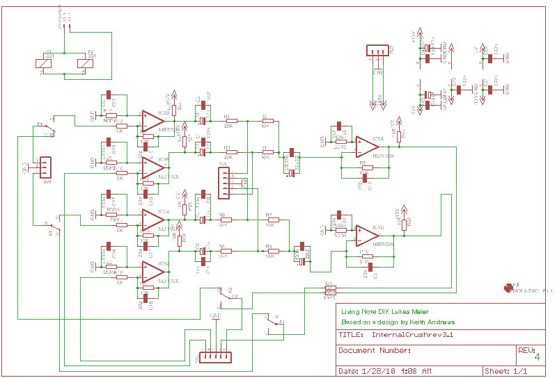
design goal here was just to have something everybody can etch and build for
little $ so of course it's about tormenting as much good sound out of the 5532's
as physically possible.

Then there was this balanced I/O with CnB idea floating around I had but never
quite got around to routing...might wanna look back into it some time because
it really makes sense to nest the CnB circuit right into the I/O for wet/dry stuff:

http://www.livingnote.com/prodigybilder/BalIOCnB.jpg

(Just replace TB1 and TB2 with "To TB1=Dev IN" and "From TB1" as "Dev OUT")

- made that one to help GeetarKing on his SSL talkback "listen" compressor...in
my world as far as that goes, every comp should have something like this ;)

Excepting that of course you get long trans lines for front-panel pot to actual
circuit, some kind of remote-control style thing would be cool for that one.
 
It is actually same money to use some 5532's and misc R/C's instead of
balanced line drivers/receivers, anyway....all this is same.
The reason why I love Japanese kitchen knives, it is cheapest solution
versus...chinese kitchen knives, they serves for a years and always sharp.
Same thing, I like to see one neat cheap instead of 3 chips and 10x 1% MF resistors,
like in case of balanced line driver.
Same thing, I prefer even more +/-24V supply, DOA,
and unbalanced-ground-compensated output circuit.
OT :)
 
Absolutely the way to go - back then I was all about just sticking to the GSSL norm
and especially learning "from the ground up" - so you can build your own cross-coupled
output stage with simple opamps, then you know how it goes, later just stick in the THAT
and be happy. They can laser better than we can match anyway ;)
 
Nope. Other project. But, this is really cool chip. I mentioned it like a situation with 3xopamps versus one balanced line driver. Regarding the implementaion of VU-meter with log scale,
it is possible to use current source/cap/choper, rc-clock and 32-bit register.
/resistor instead of current source for lin scale).
IMHO, nice idea:
 

Attachments

  • vumeter.jpg
    vumeter.jpg
    63.5 KB · Views: 80

Latest posts

Back
Top