NewYorkDave Mila Dual Tube Preamp Help Thread

GroupDIY Audio Forum

Help Support GroupDIY Audio Forum:

This site may earn a commission from merchant affiliate links, including eBay, Amazon, and others.
ding said:
Very nice!!!! I want to give this p2p a go but for future endeavors do you have the files to that pcb?

Thanks! I'm evaluating the preamp at the moment. I may make some changes to the layout/components if there are sonic gains to be had. Once I'm done I'll post some pdf's of the layout.

M.
 
madriaanse said:
ding said:
Very nice!!!! I want to give this p2p a go but for future endeavors do you have the files to that pcb?

Thanks! I'm evaluating the preamp at the moment. I may make some changes to the layout/components if there are sonic gains to be had. Once I'm done I'll post some pdf's of the layout.

M.

sweet, be nice to see what you did.
 
I was trying today to figure out whether there's a good place for a high pass filter. Is it correct to say that a 2.2nf cap in series after C4 will produce a high pass at 80Hz?
 
Dylan W said:
I was trying today to figure out whether there's a good place for a high pass filter. Is it correct to say that a 2.2nf cap in series after C4 will produce a high pass at 80Hz?

Might as well cut at the first opportunity so you won't amplify any bass in the further stages when it's going to be cut anyway. Switch between C3 and a cap of your choice with a shorting switch. Pick a value here for your RC filter: http://www.sengpielaudio.com/calculator-RCpad.htm

(R is the 100k pot in case you're a beginner). 10nF is a good starting point. Also see G9, which has a similar scenario.

[edit]

forgot to answer your question. 2n2 cap in series with C4 is also a high pass filter, also a good starting point. See exact answer with the above calc.

Keep in mind these simple RC networks are 1st order filters. It's not a steep slope and while 80hz -3dB point might sound good on paper it might not cut all that rumble.
 
Hello,

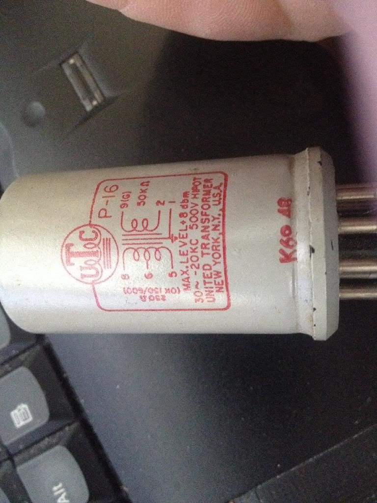
I'm considering building a Mila and am wondering if these mic input transformers would be appropriate:

087C8035-5C28-4143-ACBB-627A2D9422AC.jpg


They came from an old Harman Kardon tube PA, specifically for mic input.

In the NYD Mila schematic I'm looking at, the transformer is spec'd as a Beyer 351 310 005 and the Zobel network R4 and C1 values are 100k and 100pF, respectively. I am pretty sure my UTCs are 1:14 if that helps, but I'm not sure if I need to adjust my values accordingly.

Thank you.

-Chris
 
Thanks! I'm still in the planning stages with this, but I'm thinking about doing a pair in a 2U enclosure. Any recommendations on a power transformer that can do two channels? Looks like the secondaries should be 6.3V and 250-0-250 - is that what folks are typically doing?
 
Kingston said:
Dylan W said:
I was trying today to figure out whether there's a good place for a high pass filter. Is it correct to say that a 2.2nf cap in series after C4 will produce a high pass at 80Hz?

Might as well cut at the first opportunity so you won't amplify any bass in the further stages when it's going to be cut anyway. Switch between C3 and a cap of your choice with a shorting switch. Pick a value here for your RC filter: http://www.sengpielaudio.com/calculator-RCpad.htm

(R is the 100k pot in case you're a beginner). 10nF is a good starting point. Also see G9, which has a similar scenario.

[edit]

forgot to answer your question. 2n2 cap in series with C4 is also a high pass filter, also a good starting point. See exact answer with the above calc.

Keep in mind these simple RC networks are 1st order filters. It's not a steep slope and while 80hz -3dB point might sound good on paper it might not cut all that rumble.

For a second order cascaded RC filter, is it possible to separate the two stages and still obtain 12db/octave response? Eg implement one half at C3 and one half at C4?

Trying to implement a switchable 6/12db filter with relays, at 40/80/160 Hz (I find this very useful on the CAPI VP28).
 
I think you could do that, but again, the idea kingston said is valid. You want to filter it as soon as you can.  OTOH, a filter later in the circuit might sound interesting too, who knows?  And you could add a choice of 6dB at C3, 6dB at C4, or 12dB total.  I would think the valves woud isolate them enough to give you the full 12dB. 

consider doing parallel caps instead of switching them out completely. Probably less chance of noise, even if using MBB switches.  For example, in the C3 example, keep the smallest cap always in circuit, then have your switch add different caps in parallel to raise the value (and lower the filter frequency until "off").  You should be able to do this on one rotary switch with maybe 2-4 poles, and a toggle to switch 6dB/12dB (basically shorting out the rest of the caps in the second part of the filter). 
 
Hi All ,        I have finally finished my dual Mila and couldn't be happier.  I used Kingston's turret board layout, Cinemag CMMI-10C input, CM-9589L output as he used also. I had a custom PT made from Avel Linberg , secondaries - 220@100ma , 2x 9v@2A , 12v@500ma , 45v@80ma.
        I perf-boarded the PSU's - used the Gyraf G9 HT circuit modified with help from ruffrecords  from another project , used the heater circuit from the G-Pultec, wired the 9v secondaries in series and put a 5k trimmer in place of the 1k8 resistor to set it  for 12.6vdc heaters, used the SSL9k phantom circuit and used the G-Pultec heater circuit again with a trimmer to set 12vdc for power ON indicator.

Everything seems to be working very well, all voltages are close or spot on, it sounds fantastic, no buzz or humm thanks to Kingston's build documentation.

Many Thanks to NewYorkDave, Kingston, ruffrecords and all , I have learned so much ... and have so much more to learn  :)

  here is a link to more pix  -  https://goo.gl/photos/145iDA6U4YqE9LsK7
 

Attachments

  • Face 008.jpg
    Face 008.jpg
    78.7 KB · Views: 92
audiophreak said:
Hi All ,        I have finally finished my dual Mila and couldn't be happier.  I used Kingston's turret board layout, Cinemag CMMI-10C input, CM-9589L output as he used also. I had a custom PT made from Avel Linberg , secondaries - 220@100ma , 2x 9v@2A , 12v@500ma , 45v@80ma.
        I perf-boarded the PSU's - used the Gyraf G9 HT circuit modified with help from ruffrecords  from another project , used the heater circuit from the G-Pultec, wired the 9v secondaries in series and put a 5k trimmer in place of the 1k8 resistor to set it  for 12.6vdc heaters, used the SSL9k phantom circuit and used the G-Pultec heater circuit again with a trimmer to set 12vdc for power ON indicator.

Everything seems to be working very well, all voltages are close or spot on, it sounds fantastic, no buzz or humm thanks to Kingston's build documentation.

Many Thanks to NewYorkDave, Kingston, ruffrecords and all , I have learned so much ... and have so much more to learn  :)

  here is a link to more pix  -  https://picasaweb.google.com/audiophreeek/NewYorkDaveMila?authuser=0&authkey=Gv1sRgCLO_4a79lOyAfg&feat=directlink

nice work! she looks beautiful.
 
Great idea with those aluminum bars as tube etc. support. Good to know the layout and grounding was proven once more. Although you certainly could've taken that power on light from heater PSU directly, with no need for separate one. Then again those parts are cheap so who cares.

9+9=18VAC into 12.6VDC is a big drop and a lot of heat with these 12AV7 currents. Which you might have already noticed. I've had some projects fail after some years because of similar high expectations from heater regulators. Keep this in mind if planning very long term high use installation. You may have to deal with this at some point later on, no matter high big the heat sink.
 
Hi All ,        I have finally finished my dual Mila and couldn't be happier.

Beautiful! The turret board and tube mounting looks great.
How are the big output caps secured at the side? It looks like they might just be held down with some adhesive putty. I would strongly recommend mechanically fastening those, if they are not.
You don't want them coming loose and bouncing around in the case with high voltage.
 
Thanks everyone  :)  I need to wire tie and tidy up a bit  ;D

  Kingston , I originally  wired the power ON from the heaters, but they were too bright and when I put a larger dropping resistor in-line it got real hot, so I built up the second 12v psu and trimmed it down- I think its actually at about 8vdc... and you are correct on the Heater regulator , even with that heat sink it gets VERY HOT , I used a LT1085 votage reg. its rated for 3A and at the 12.6vdc for the heaters I should only be drawing about 1A for all 4 tubes. I remember reading your post on that and will definitely keep an eye on it... and thank you again for all your help.

dmp, the output caps are held in place by a horizontal snap-in type clamp , like the image below.

  Thanks again everyone , very happy with this build  :)
 

Attachments

  • horizontal clip.jpg
    horizontal clip.jpg
    82.1 KB · Views: 37
This is a Stock 12Av7 version I'm asking about.

Wondering if any kind souls could walk me through the way the negative feedback is actually wired?
I'm getting confused with the switching options.
The schematic is hard for me to understand around V1's cathodes. Further confusing the NFB switching.

I've got one built up.  And voltages are on spec.  It is awfully distorted, albeit passing audio.
My bet is that my NFB arrangement/wiring is bunk!
Thanks
 
try this page - http://groupdiy.com/index.php?topic=38699.msg700446#msg700446

  You should read the whole thread , some incredible insight from Kingston ,  towards the bottom of the last page I scribbled a graphic on how I wired my range switch with Kingston's patience and help  ;D     
 
hope this helps
 
Just built one of these preamps and they hace TONS of gain... Using a 1:10 Input transformer (lundhall 1578) and a 1:2 output transformer I was getting more than 80dB's of gain  :eek:

I wired the output transformer to 1:1 and think I will make 1:5 for the input...

I have to redo the layout, it's quite noisy (and messy) right now.

Can't tell about the sound, I don't have a mic around, but it was a funny build, I really like to build p2p, and working with tubes helps understanding the basics, really enjoyed this build.
 

Attachments

  • IMG_20160117_204631-1024x576.jpg
    IMG_20160117_204631-1024x576.jpg
    166.3 KB · Views: 72
Redid my layout and it doesn't work anymore, I think I've messed up something, not so worried actually, just a bit of calm and look everything good.

It's surprising how the tubes are really tolerant to wiring mistakes, and how caps keep charged! Yesterday, when I arrive to the shop, after more than 24 hours turned off I still got a zap in my hand, measured with DMM and found 250V in the B+ rail.  Luckily I had a 470r/5W resistor at hand.

I have to say I fell in love with the p2p builds....
 
dirtyhanfri said:
Redid my layout and it doesn't work anymore, I think I've messed up something, not so worried actually, just a bit of calm and look everything good.

It's surprising how the tubes are really tolerant to wiring mistakes, and how caps keep charged! Yesterday, when I arrive to the shop, after more than 24 hours turned off I still got a zap in my hand, measured with DMM and found 250V in the B+ rail.  Luckily I had a 470r/5W resistor at hand.

I have to say I fell in love with the p2p builds....

I'm working on a MILA also (p2p, dual). Ordered most parts.
I will be using LL1935 (which is a 10:1 DI transformer, but Lundahl also recommends it for mic input applications). I didn't realise you could use LL1578.

I think the big EI core power transformer might be what's causing the noise problems. Try putting outside the case, of shield it with some iron.
I will be using a toroid (less magnetic radiation), but I'm also going to shield it - just to be sure.
 
Back
Top