radiance
Well-known member
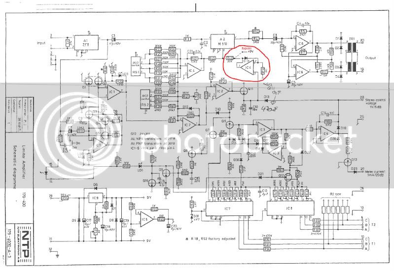
goldvasser said:Hi PRR !PRR said:> the selection of the recovery times. i'm a bit stumped
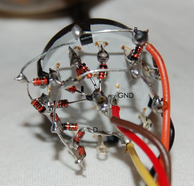
It would also be possible to do this with a simple 1-pole 8-throw switch. Ground the wiper. Start connecting diodes, band-end to the switch, to the ABC terminals marked "0" in Note 2. Position 0 has no diodes. Pos 1 has one diode to pin A. Position 7 has three diodes, to A B and C.
Do you have a shemo or something to do that ? I must confess that I don't see the picture to realise this excellent trick !
Cheers !
Bruno.
I don't think there will be a schematic for this. On the positive site..this is an excellent learning oportunity ;D
read this info on diodes and you'll probably know how to make this switch
http://www.kpsec.freeuk.com/components/diode.htm
Another thing you could do is using a 6 dip switch. I found that I only used one setting. However, to find the setting YOU like best, it's easier to have a rotary so you can instantly switch between settings.


")