ntp limiters

GroupDIY Audio Forum

Help Support GroupDIY Audio Forum:

This site may earn a commission from merchant affiliate links, including eBay, Amazon, and others.
Radiance, I totally agree with you on your point of view about using your ears vs being influenced by your eyes. But I have this great front layout with all the meters and I want them to work as they should! ;D This is just my demand as someone who builds gear and wants it to function and look good, not from a musical perspective... I´ll see if anything changes when I recap my units otherwise I´ll just connect the meters + when in link mode. I know, that makes double the load and the meters are out of calibration, but at least they react the same indicating the stereo link.

@matthias: I just tried your suggestion: nada  ;)

Thanks guys!
 
how are you guys powering these? i've got 2 that i'm powering with 24V and they do nothing.

+V on pin 29, 0V on pin 31. PSU works, also powers 2 TAB mixer channels. i'm measuring 24V on the 3 LM317 pins, so power gets in there. but no led, no sound.. am i missing something horribly obvious? and this is going on with both of them.. so i don't think it's one broken part either.. are there any other points on the board to measure voltage?
 
On the group diy gmail account is an pdf about these ntp limiters containing all wireing info.

I build mine exactly like that...I also replaced all "red can" caps btw...
 
i think i have that pdf.. with description, pinout, etc, right? it's what i used to wire mine too. i was more referring to the power supplies itself, and i read something about that switchboard being necessary? i can't figure out, unless both limiters are broken, why i'm not getting any action from them when i get 24V internal on IC9, so there is power inside the machine..

before i start recapping, i'd like to see what condition the limiters are in overall..but good tip!
 
some more info: i seem to have power everywhere, yet the limiters won't work. no power led, a little bit of sound coming through but no limiting action whatsoever. i have 24v on the lm317, the lf412, the 2 4051's and the ne5532.

any ideas?
 
Hi all,

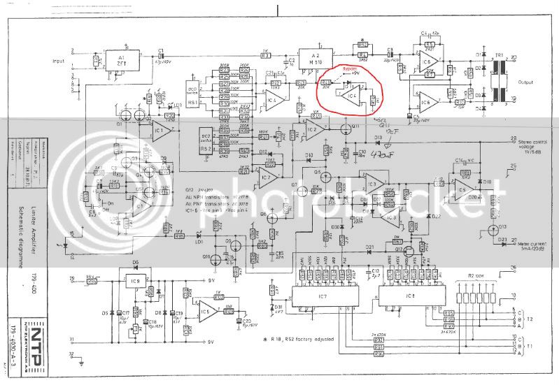
Does anyone know whether c10 in the attached schematics needs to be changed to 470nF and if so what affect does it have on the limiter.

Many thanks for any advice as I have a pair of these limiters and am busy recapping the electrolytes and noticed the hand written note on the schematics.

Cheers
Craig
veermaster said:
This model E I was talking about has a Bypass switch on the frontplate (the others don´t). This is what it does:

179-400schemoBypass.jpg


I tried this with another module and it works. Well, the meter still shows limiting but I could just deconnect it by the same switch.
But I still don´t have a clue how to stereo link these modules. Linking Pins 28 of two such modules just does not work  ???
 
Hello

I am having troubles too to link my pair of NTP 179 400.
I joined both units pin 25, is that the correct way?

Also, another question regarding the controls, the gain rotary switch is controlling the sidechain / detection gain or output gain?
On my unit if feels like the higher the "Lim Level" setting, the lesser limit going on... Is this correct?

A bit lost with the settings for now one... but since I am tinkering with croc clips, maybe it's will be clearer when they'll be racked with a true bypass and everything.

According the schematics "pre emphasis" seems to limit mainly above 1K depending on the input signal?

I have the version without the bypass switch.
 
It seems to me that connecting pin 28 will link the control voltages to obtain equal gain reduction for stereo.  Has anyone else tried this?
 

Attachments

  • NTP 179-400 pin assigns.jpg
    NTP 179-400 pin assigns.jpg
    294.4 KB · Views: 25
Hello!

I am in the process of racking my pair, and trying to figure out stereo link... I'll keep you guys posted.

I would like to add a LED Gain Reduction meter to my limiters, in order to be able to keep track of how much dBs I am limiting, since it is a pretty fast limiter.
I was thinking of using a pair of Pico Comp meter cards, or any other alternative? I like the option of switching between 10dB or 5dB scale for the 10 LEDs...

Has anybody tried that?

Thanks a lot

Cheers
 
radiance said:
On the group diy gmail account is an pdf about these ntp limiters containing all wireing info.

I build mine exactly like that...I also replaced all "red can" caps btw...

Do these documents still exist?
If so could someone email them to me at:
stitchproductions at gmail dot com?
I checked the tech docs section with no luck...
 
Great cheap solution to bring the gain and lim functions
to front panel - greyhill 10pos BCD rotary for 10 bux:
http://www.ebay.com/itm/281287437093?_trksid=p2057872.m2749.l2649&ssPageName=STRK%3AMEBIDX%3AIT
 
I also had meter problems in stereo link mode. My solution is:
not to hardwire pins 28 together, but use a resistor of 1k2.
Now they are like 95% linked, could even be more interesting then hard wiring.
I also bridged R89 with a wire to get more meter readout.
I had a difference in overall gain of 0,3 db between both channels, so I added a 120k resistor on the loudest channel over R5.
Are you guys using the standard recovery time? What is your favorite setting when it comes to recovery times?
 
I also bridged R89 with a wire to get more meter readout.

Did you eliminate R89 1K8 on both units?  How much of an affect did this have on the meter display?  What kind of meters are you using with the limiters?
 
I used 1mA (brand Hansen) meters. Yes I eliminated R89 on both units. Actually I've put  a resistor over R90 to to calibrate the meter. I don't remember the value. Must have been higher than 15k I guess.

meter goes up to 1 ma equals 10dB. So if the meter shows  .4 I have 4 dB of gain reduction.
 

Latest posts

Back
Top