Ok I read that a few times and couldn't get what you were asking...but a quick Google search tells me you must be asking about Deltron GAC-7 power supply cable.
")
Here's how I would use this: the two thick cables (red and blue according to the datasheet) I would use for heater and ground, since these have the lowest resistance per foot. So declare red for heater+ and blue for ground. The current flow through B+ is minuscule compared to the heater so your ohms are best spent on heater and ground.
Here's the ground scheme:
1) Inside the PSU: PSU board ground connects to the 7-pin XLR connector. The docs use pin #7 right in the middle. This ground is also connected to the PSU enclosure via a short jumper to the brass tab on the XLR connector which goes to the chassis via the housing itself.
2) Inside the PSU, the 3-pin XLR connector has pin 1 connected to the shell via a similar brass lug.
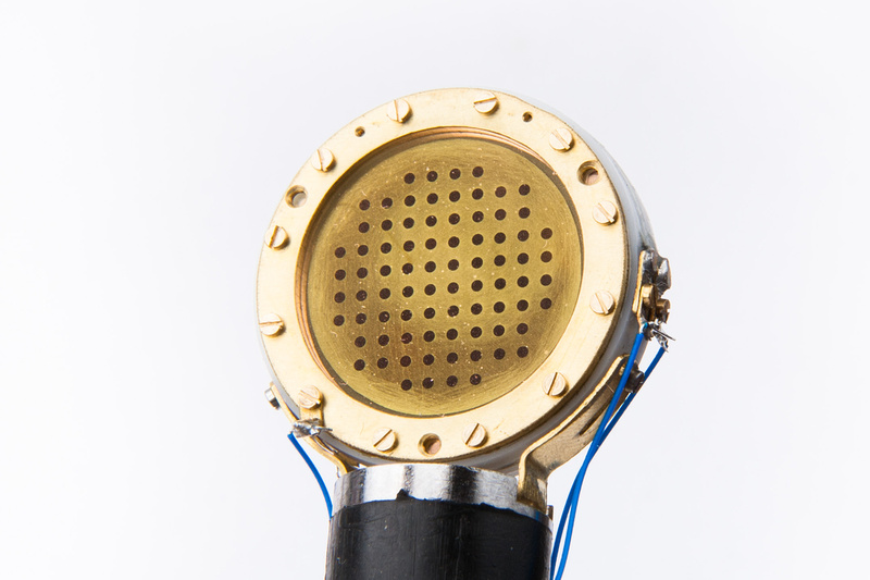
Inside the mike: pin 7 goes to the PCB "P6" node and transmits the PSU ground right to the PCB ground. The shell of the XLR cable (which is the cable shield) is tied to the microphone body via the 7-pin connectors brass retaining screw, which is also strapped to the ground wire to pin 7. The circuit ground is bonded to the microphone body via the PCB mounting screws as well. Thus all of these things become "ground" when it's all bolted together.