Official C12 Clone - Build and Support Thread

GroupDIY Audio Forum

Help Support GroupDIY Audio Forum:

This site may earn a commission from merchant affiliate links, including eBay, Amazon, and others.
chunger said:
Category 5 said:
kcatthedog said:
hi,

if i want to use a mullard 12at7, do i need to mod the mike ?  I have been told voltage should be ok ?

thx!

Looks ike you might just need to change r17 to 47k in the mic and re-bias.

The other stuff was for the silver mica conversion only, right?

Please read the relavent posts carefully.  The B+ section of the power supply is passive.  2 resistors in the psu also need to be changed to account for the new tube.  This was explained in detail a few posts back.

Got it Chunger.  R1 snd R2 need to drop in value to account for the increased current demand of the AT7.  In all the conversion only involves those three resistors though, right?  I mean the silver mica and output cap substitutions from the pictorial were an additional unrelated mod.
 
Yes.  The three resistors are for the 12AT7 conversion:  the cap changes (silver mica and output cap) are just to show BOM diversity and stuffing options.
 
Matador said:
Yes.  The three resistors are for the 12AT7 conversion:  the cap changes (silver mica and output cap) are just to show BOM diversity and stuffing options.

Got it.  Makes me think that (with the regulated supply upcoming) internally switchable plate resistors would allow maximum flexibility.
 
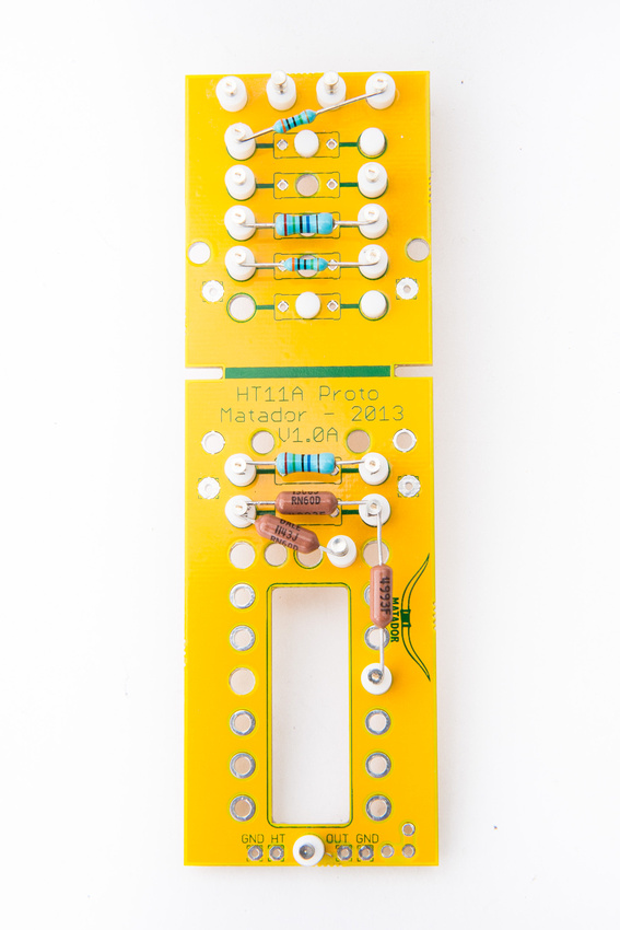
OK. . . a bit of fun with the new "C12 prototyping PCB" that Matador recently designed to fit the HT-11A donor microphone.  With all this jabber about isolated circuits vs. pcb, I thought I'd like to show the flexibility and options our kits have for building pretty much whatever you want inside the HT-11A donor platform cleanly and solidly.  This allows for a true isolated point to point construction of the circuit while maintaining all of the wiring and noise benefits of a proper ground plane.

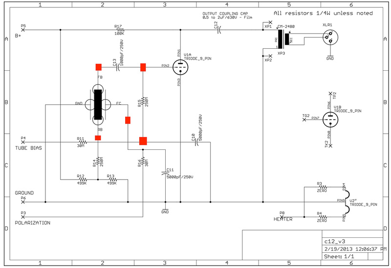
This is not meant to be a paint-by-numbers step-wise guide as anyone laying out a design for point to point wiring should refer to the schematics often, but of all the build possibilities on the Proto PCB, this is perhaps the easiest because the "regular" C12 PCB set provides an almost direct road map for the required wiring connections. 

For reference, even though I am teflon isolating almost the entire circuit in this build, and we feel our standard C12 PCB design is a robust and proven execution of the circuit, Matador informs me that technically speaking, these are the only Hi Z nodes in the circuit that would be of any small significance to isolate on teflon standoffs.

p822089548-4.jpg


It should be noted that all of the techniques used in this demonstration of the new "prototyping pcb" can also be deployed on the regular C12 PCB if one wishes to isolate any part of the circuit with teflon and wire those portions point to point with silver teflon wire.

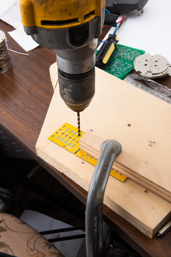
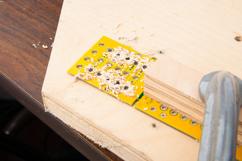
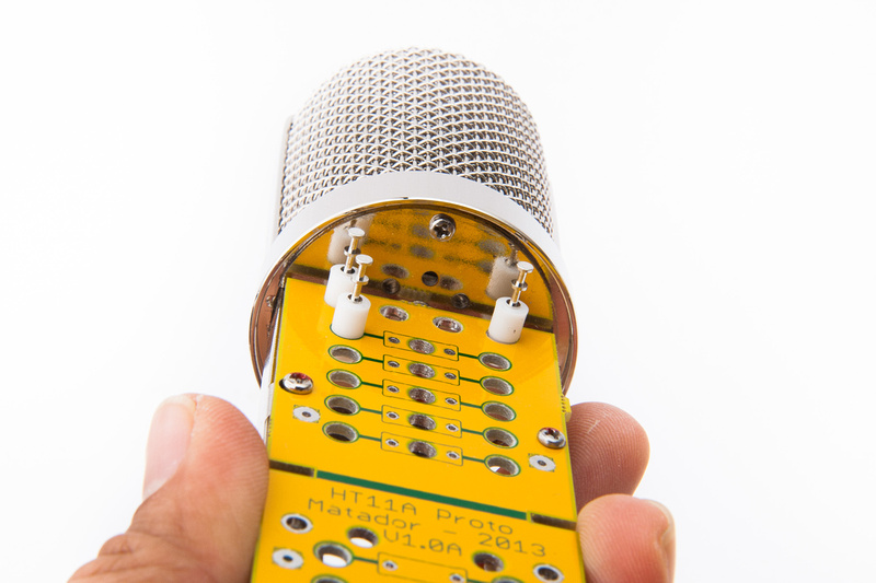
To start, I drill out the required holes to mount keystone teflon standoffs.  I use a 9/64 inch drill bit which worked well for a good friction fit.

p619299648-5.jpg


p1034541558-4.jpg


A quick test fit revealed that the outer edge standoffs would be too tall to fit inside the HT-11A tube.

p584630997-4.jpg


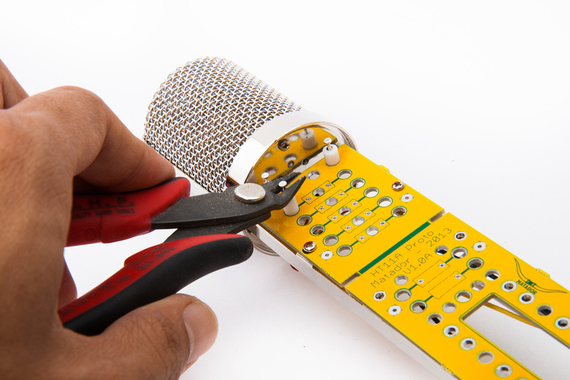
Wire cutters make quick work of cutting off the top section of the standoff.

p916521204-4.jpg


And clearance has been restored.

p560871623-4.jpg


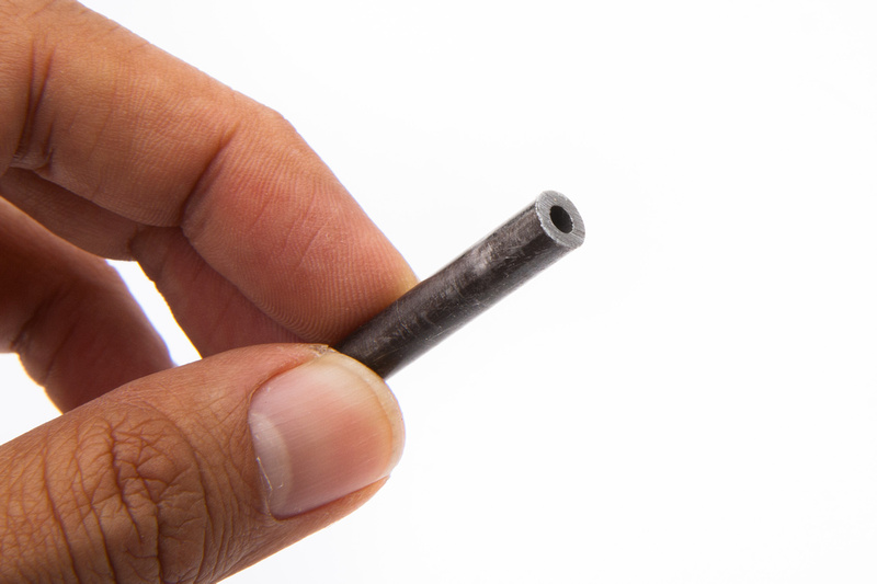
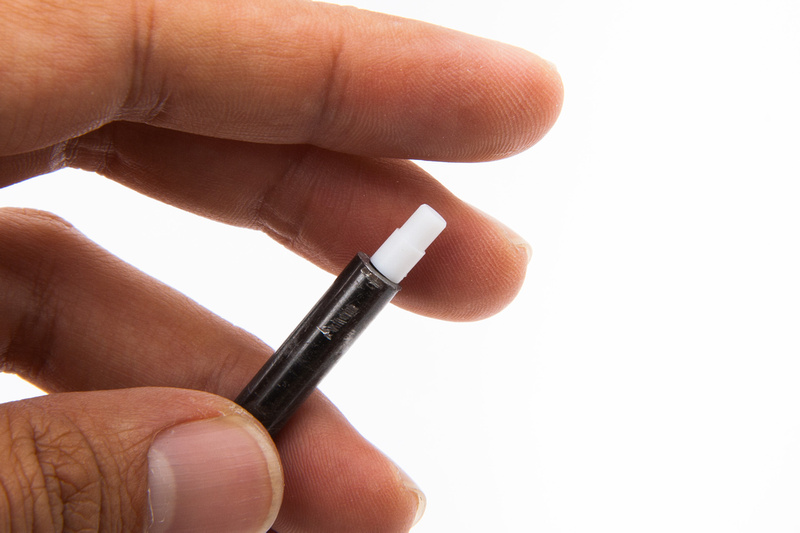
This is a tool I purchased from tubedepot.com when I was building a turret board based point to point power supply for ioaudio's mk47 microphone kit.  It is used to drive turrets into the board without damaging the fragile turrets.

p695102082-4.jpg


I used this tool to help hand press the teflon turrets into the PCB.  A bit of side-to-side wiggling is necessary to seat the teflon turrets all the way in.

p757046355-4.jpg


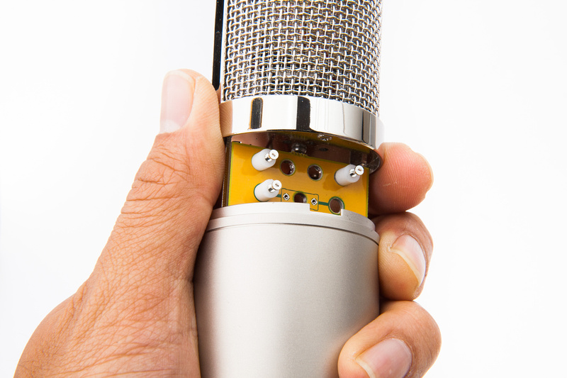
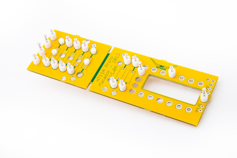
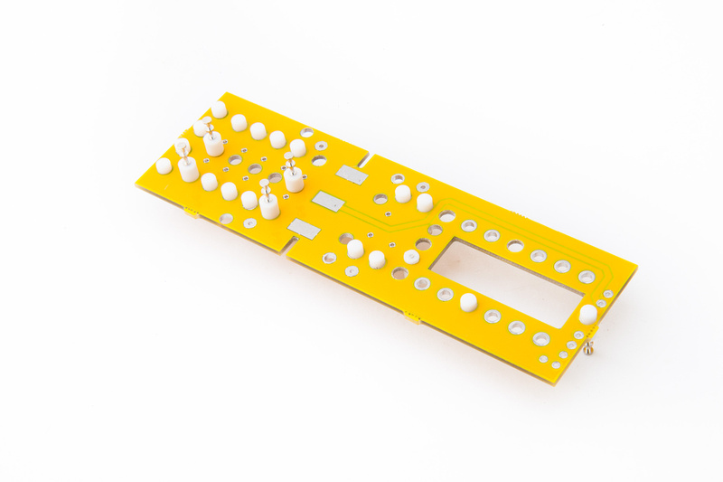
And, here are the turrets installed.  I'm sure there are prettier and more elegant solutions in terms of layout, but I think this will work.

p595293339-4.jpg


p1052924648-4.jpg


Next, I install all of the components except the polystyrene capacitors because those are sensitive to the 90% isopropyl alcohol I use to clean the assembly.  It is much easier to clean when you can dunk the entire assembly into the liquid and scrub with a toothbrush, so I leave the sensitive components for last.  I install all components with a 1/2 turn around the turret post to make sure each connection has a solid mechanical contact before soldering.

p812353068-5.jpg


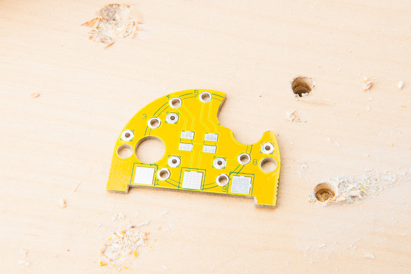
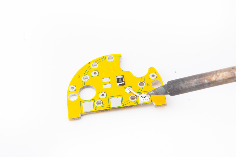
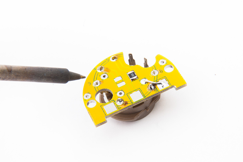
The only PCB trace that I will utilize in this build is the heater supply voltage.  I will also utilize the "2nd half" of the tube as my other microphone build uses the "1st half" this way, I will have a pair of mics I can swap tubes between and double up on my tube life expectancy.  The Grid connections (pin 2 and 7) are already isolated on Matador's PCB, and the Cathode node (pin 8 ) simply connects to the ground plane, so I drill out the Plate node (pin 6) so my build will be fully isolated except for heater supply (pin 5) as previously noted.

p707393754-4.jpg


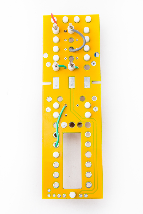
The jumper for heater supply is installed and an efficient jumper to ground installed for our Cathode node (pin 8 ).

p636225455-4.jpg


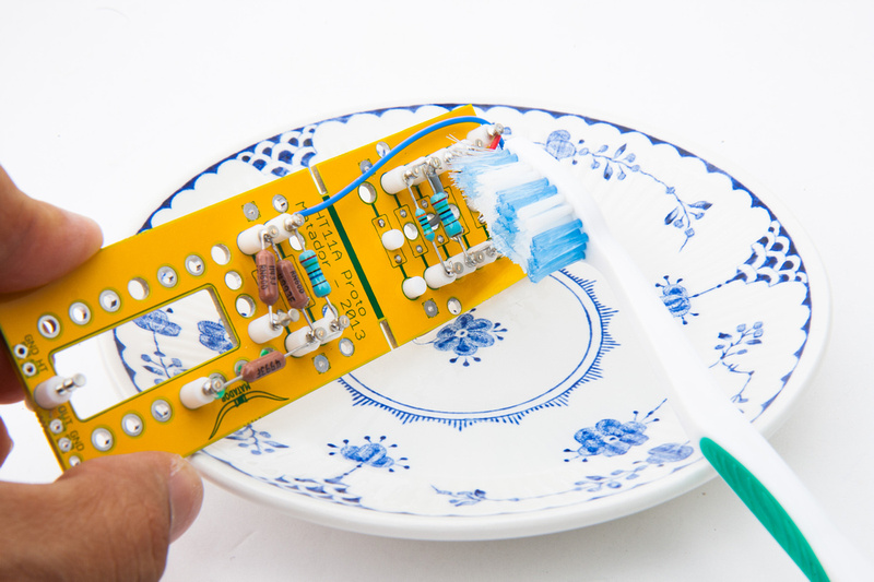
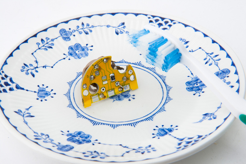
And we dunk the entire mess into 90% isopropyl alcohol and scrub the solder flux off.

p958833332-4.jpg


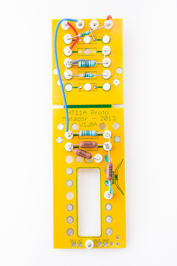
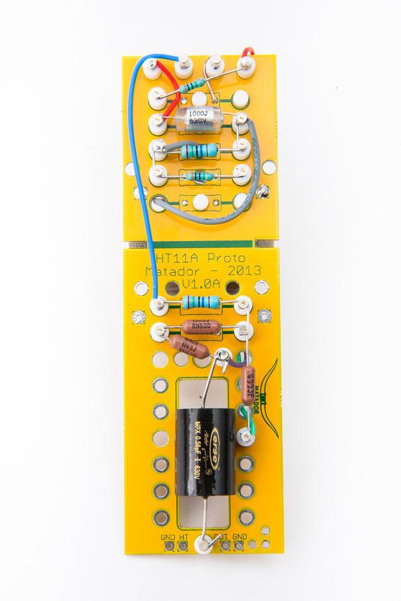
Next, I solder in my resistors and make my PCB wiring connections.  Some utilize leads cut off from my resistors and the rest use silver teflon wire.

p757730151-5.jpg


p779676572-5.jpg


And, it's never a bad idea to clean thoroughly, so I dunk the assembly in isopropyl alcohol and scrub.  The reason I use a small plate is so I can change the alcohol often.  The more you use the solution, but more flux is dissolved into it, so changing the liquid often is helpful.

p992320022-4.jpg


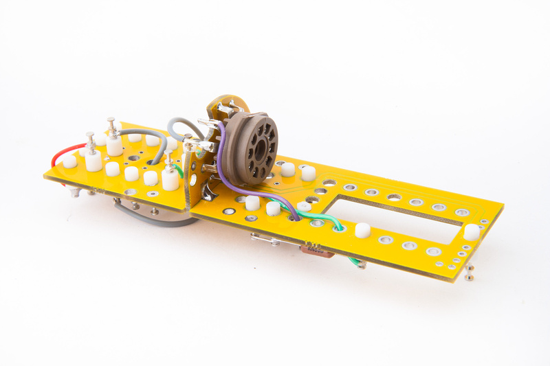
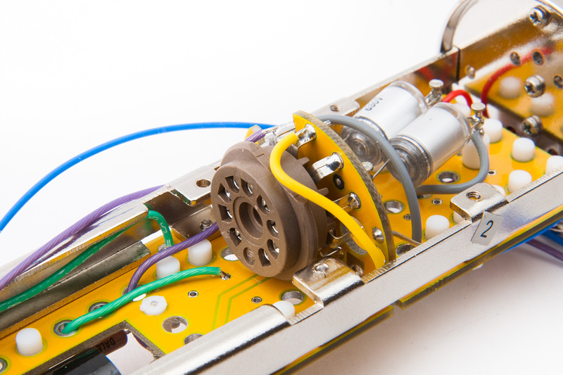
Next, the tube socket is soldered in.

p999125240-4.jpg


and cleaned thoroughly.

p1020889020-4.jpg


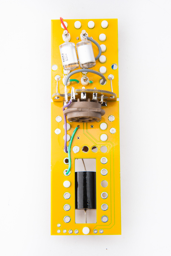
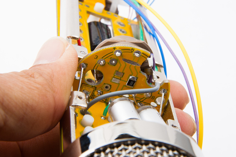
The tube board is then soldered to the main PCB and connections for the Grid (gray wire) and Plate (purple wire)  are made point to point.  This is the last opportunity to dunk the entire assembly into the IPA solution, so I clean one last time very throughly

p1042529336-4.jpg


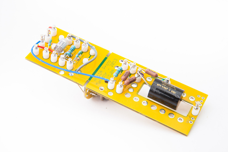
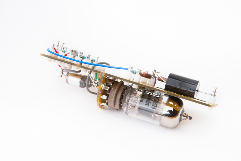
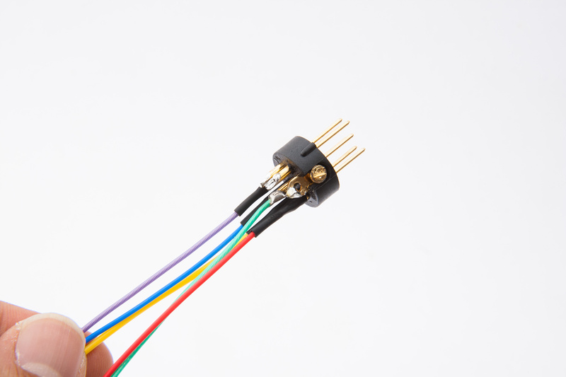
. . .and then install the capacitors completing the microphone PCB build.  More connections will need to be made to the 7 pin XLR jack at the base of the microphone and to the output transformer.

p741316671-5.jpg


p119911331-5.jpg


p5256590-4.jpg


p105387839-4.jpg
 
scott_humphrey said:
Very cool!

Could you please share the part number for the teflon-based turets? Thanks in advance.

Keystone 11308.  There is also a low-profile one that fits in the same hole size (probably doesn't need to be trimmed, but it's also much closer to the PCB):  the 11320.
 
I want to apologize up front if this has been asked a billion times already.  I'm new to group diy and taking an interest in these mics and hoping to build some in the future.  My question is,  is there a localized place to find soundclips or reviews of these builds whether it be the C12 or U47 clones?  Thanks
 
chugging right along, I start making my 7 pin XLR connections.  I recycle the stock connector and replace all of the wires with new silver teflon wires.

There's no particular right or wrong about color selection, but I designate:

pin 1 red (B+)
pin 2 yellow (heater)
pin 3 blue (pattern)
pin 4 purple (bias)
pin 5 - open for now (transformer audio -)
pin 6 - open for now (transformer audio +)
pin 7 - green (ground)

pin 7 is jumpered to the chassis contact tab with a cutoff resistor lead.

p180169739-4.jpg


As I start to wire up the various connections, I realize that the heater trace runs directly under the metal frame rail.  We know solder mask has a good formulation, but I do not like the situation very much.  A few solutions cross my mind. . .

- washers between the PCB and frame rail to give a little air gap
- a little electrical tape along the top of the frame rail

What I decided to do was since I already have a nice, long yellow wire attached to take that directly to the tube socket.  Since it was about 5:00AM and I was not quite thinking straight, I decided to disable the trace by cutting it right at the tube PCB with a dremel cutoff wheel.

p330492799-4.jpg


In hindsight, that was kindof silly because I could have just as easily removed the 0 ohm jumper resistor that is directly under my cut!!!  idiot!  Well, either way, trace has been neutralized and the build continues.

I recall there is some space in the through hole where the tube socket solders into the pcb, so I heat the node while simultaneously inserting my yellow wire to make a quick and solid connection.

p305527764-4.jpg
 
Matador,
When converting the mic to use 12at7 tubes... what voltage readings should we be looking for? I'm assuming 120V for B+, 6.3 for Heater? Right? We adjust the bias (approximate voltage reading please) for the a new plate voltage value. What plate voltage should we be looking to have with the 12at7 tube... between 60-80 Volts? Please advise when you can. (P.S. I love my mic! :)
 
pmcorbett said:
Matador,
When converting the mic to use 12at7 tubes... what voltage readings should we be looking for? I'm assuming 120V for B+, 6.3 for Heater? Right? We adjust the bias (approximate voltage reading please) for the a new plate voltage value. What plate voltage should we be looking to have with the 12at7 tube... between 60-80 Volts? Please advise when you can. (P.S. I love my mic! :)

Yes, once the resistors are changed, the voltages should be trimmed just like the previous 6072A design:  trim B+ to 120V, heater to 6.3V (measured at the tube socket), and -1V bias.  Plate voltage should be about half of B+, but will range from 50V up to 80V depending on the actual current in the actual tube.
 
I get no reading on any of my Multimeters on the two blue wires of my T14. Two Red reads 21,9 ohm. Is it broken?

/Michael
 
Hey Mat.  Any opinions in difference in sound with the At7?

I've been auditioning 6072 tubes and find a wide variance in tone from tube to tube.  An ugly old eBay square getter ge 5 star is kicking all the other tubes butts.  So rich and creamy thanks to a lot of distortion.  Hoping to find a match for it. 
 
Category 5 said:
Hey Mat.  Any opinions in difference in sound with the At7?

I've been auditioning 6072 tubes and find a wide variance in tone from tube to tube.  An ugly old eBay square getter ge 5 star is kicking all the other tubes butts.  So rich and creamy thanks to a lot of distortion.  Hoping to find a match for it.

Unfortunately I don't have any apples to apples comparisons:  the new mike I built with the 12AT7 had different caps in the audio path and a completely different capsule as well.  Not very useful for comparison purposes to the versions I had built previously.

I think aside from sound the biggest advantage would be availability.  It's MUCH easier to find low-noise 12AT7 tubes out there at much better prices.  I'd suggest you contact Christian Whitmore or some other tubemonger you trust and ask for some subjective opinions.

In *my specific test case*, I used a GE 5 start 12AT7 from 1959.  I had purchased a quad of them about 10 years ago to use as spares for my Sovtek Mig 100B tube bass amp for the phase splitter position.  I had previously burned these tubes in using that amp for about 50 hours each.  I tried all four of them, and 3 were moderately microphonic, and rang at about 800Hz when tapping the mike body on the side.  The 4th was pretty quiet.  I think I got the quad off Ebay for about $50 at the time.  I can't say they sounded very different to the 6072A tube with the test beater capsule I normally use on new builds for initial testing.
 
Hi Matachung et al,

I just had a quick question re the PCB.

I'm not sure I'm being over-OCD about the isoprop cleaning of the board but after a moderate amount of scrubbing I am able to remove all of the flux from around the board but am left with a slightly sticky residue coating the whole board. Is there are coating on the PCB from manufacturing that I am not completely removing? Should I just keep on a scrubbin'?

Thanks for this project guys... the twins are due to be born into a loving family any day now....

Regards,

Matt
 
hey, so thx to cat5 my re and re to run the mullard tube went fine.  I ordered the parts from Mouser: great service overnight from texas, pulled the two resister (r1/2) from psu, dropped new 33k, bit tricky and installed new resister in mike: simple but lifted turret so had to resolder. setting b+,h and bias was good , bias was tricky, due to interaction between b+ and bias but easy does it with bias: till it settles.

The c12 sounds fine with the mullard :very pleased: again thx the matachunger , cat5 and bowie for tube recommendation and Brian Fox for TC cap and QC!
 
Woot said:
Hi Matachung et al,

I just had a quick question re the PCB.

I'm not sure I'm being over-OCD about the isoprop cleaning of the board but after a moderate amount of scrubbing I am able to remove all of the flux from around the board but am left with a slightly sticky residue coating the whole board. Is there are coating on the PCB from manufacturing that I am not completely removing? Should I just keep on a scrubbin'?

Thanks for this project guys... the twins are due to be born into a loving family any day now....

Regards,

Matt

Change to fresh isopropyle alcohol.  As you dissolve more and more flux into the liquid, it will start to leave a residue on the board.  A fresh batch should do the trick in removing the remaining residue.
 
Hi Guys,

I have just completed 2 of these bad boys and..... no love  :(

Both have similar issues but I suppose we'll have to sort them one at a time.

Both PSU's went together no problem and I can dial up the appropriate voltages as need with the mics connected.

When I connect both mics, their output is really low.

For example - on this first one I have the preamp (Vintech 573) with trim at 70dB and output fully up and I'm getting a bunch of hiss and really quiet output (barely audible).

I have quadruple checked all my connections/joints, swapped the capsule out, changed tubes (am using 6072's from Christian). I have checked the trafo and  it is wired the correct way and reading proper resistance on both windings.

Voltages at tube pins:

9: 1mv
8: 0.6mV
7: - 0.975V
6: 69V
5: 6.3V

Any suggestion where to start troubleshooting will be greatly appreciated.

And apologies in advance if it ends up being something very n00bish.

Regards,

Matt

Addit: So I am a muppet.... I neglected to solder the two "bottom" pads of the tube socket board, which I subsequently read complete the circuit. Completed same and bingo... output... lot's of beautiful output. Now to reinstall my Beeznees... :) Thanks Matachung for an amazing project
 

Latest posts

Back
Top