RuudNL said:Mmmm.... I'm afraid no resistance means: no conductivity by the copper.
In other words: the winding is broken!
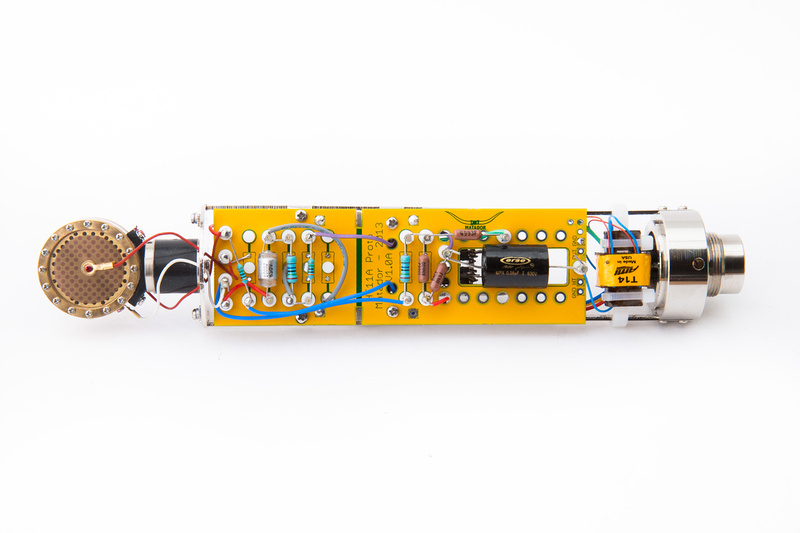
Chunger: if you see this i have sent you an email regarding exchange of the broken T14.
Michael
RuudNL said:Mmmm.... I'm afraid no resistance means: no conductivity by the copper.
In other words: the winding is broken!
Category 5 said:All cool stuff Chunger. Are you still involved in jessJackson's 251 project? It was looking really clean and I love the idea of the pattern switching happening in the mic with relays.


aamicrophones said:The CM2480 has to low a turns ratio to be used with a single plate output circuit. It only has a 10:1 ratio and you need something like the T14 which has a 17:1 ratio.
The plate resistance is upwards of 22,000 ohms the CM2480 has an impedance ratio of 100:1 (square of the turns ratio). This means the 1.2K high mic input impedance of a 1073 would present a 120K load to the tube which wants to see a load of >220K to have no loading effect on the plate. The T14 has a impedance ratio of 286:1 which will not load the single 6072a plate circuit.
Now, you could get away with the CM2480 if you were going into one of the new transformerless preamps with a 5K input impedance but most folks want the vintage microphone sound and preamp.
The 2-stage CCDA circuit is a much better option as it is more HiFi than the original C12 circuit having an output impedance of 600 ohms.
You can use a transformer with a ratio of 5:1 ( impedance ratio of 25:1). You can use the CM2480 with impunity when driving it from 600 ohms... look at the specs on the Cinemag site.
Cheers, Dave
aamicrophones.com
jandoste said:Hey guys,
I finished my build but no love... Its sound is very low! and I check everything so all good now!
I am not sure just wiring the T14 ... I didn't check the "-" "+" for XP1 (+) and XP2 (-)
it was the same values as like Chunger's T14
"The blue wires read 930R and will connect to the pcb to the terminals labelled XP1 (+) and XP2 (-)."
Do I must find the sides "-" "+" ? I didn't think the T14 has these sides....
Thanks
Jan
pasarski said:jandoste said:Hey guys,
I finished my build but no love... Its sound is very low! and I check everything so all good now!
I am not sure just wiring the T14 ... I didn't check the "-" "+" for XP1 (+) and XP2 (-)
it was the same values as like Chunger's T14
"The blue wires read 930R and will connect to the pcb to the terminals labelled XP1 (+) and XP2 (-)."
Do I must find the sides "-" "+" ? I didn't think the T14 has these sides....
Thanks
Jan
+ & - only affects on polarity. Try to "flip" the trafo. Some T13's have in and out backwards, maybe T14's also.
[/quote]jandoste said:Thanks Pasarski for your response!
Which red is +/- I didn't check that but I really want to know why the mic's sound is very low
Category 5 said:jandoste said:Thanks Pasarski for your response!
Which red is +/- I didn't check that but I really want to know why the mic's sound is very low