official GDIY51PSU Help & Support Thread

GroupDIY Audio Forum

Help Support GroupDIY Audio Forum:

This site may earn a commission from merchant affiliate links, including eBay, Amazon, and others.

[silent:arts]

Well-known member
Joined
Jun 4, 2004
Messages
5,235
Location
Berlin, Germany
due to request:

Schematic
Components

the 10n Cs over the bridge rectifiers are not needed. if you like them - stuff them, if you don't like them - leave them out ;D

the PCB is designed to power up one Rack, with 12 modules installed needing the max power of all 5 rails.
however - this will never happen, depending on your modules installed it might be possible to power up 2 full Racks.

I changed the copper weight for rev02, which resulted in a more orange than yellow color, but who cares :eek:

the PSU transformer specs I use are:
prim.: 2x115V
sek.1: 2x 24V/2x2,20A [changed specs]
sek.2: 2x 16V/2x2,20A [changed specs]
sek.3:     48V/0,25A
Cu-Foil screened
d = 100 mm  h = 52 mm
weight: nearly 2kg
ta 40/E   50/60Hz   n. EN 61558

some Mouser order numbers by ChuckD
some corrections on that by Brolik
Bridge Rectifier Datasheets

please visit chungers impressive how to build it Thread too
 
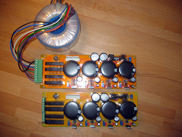
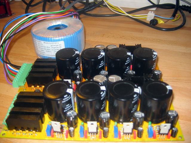
prototype in front, production run with PSU transformer:

IMG_5839.jpg


IMG_5840.jpg
 
A few nits:

With that transformer you're limited to ~1A on the main rails. Why use an LM350 in that case, instead of the more ubiquitous LM317? It looks like you're limited by dissipation not max current, and the thermal resistance of both parts is almost the same, limited by their TO-220 package.

[silent:arts] said:
the PCB is designed to power up one Rack, with 12 modules installed needing the max power of all 5 rails.

With a 2x16V/1.5A transformer this PSU can only power eight normal 500-series modules (@130mA max per rail). You'd need at least a 2x16V/2.2A transformer to feed a dozen.

Am I missing something here?

JDB.
 
jdbakker said:
With that transformer you're limited to ~1A on the main rails. Why use an LM350 in that case, instead of the more ubiquitous LM317? It looks like you're limited by dissipation not max current, and the thermal resistance of both parts is almost the same, limited by their TO-220 package.
LM317 & LM350 are pin compatible, no problem.

jdbakker said:
With a 2x16V/1.5A transformer this PSU can only power eight normal 500-series modules (@130mA max per rail). You'd need at least a 2x16V/2.2A transformer to feed a dozen.
will change the transformer specs and my order :)

jdbakker said:
Am I missing something here?
you just have the better knowledge ;)

thanks for the nits
(and, btw, thanks to Harpo who helped with this PSU too)
 
HI All

I just received a custom toroidal from http://www.sumr.com/ for this PSU. Richard Summer is a Canadian supplier that ships world wide.

Prim 115v x 2
1sec 48v @ 0.5a
2sec 24v x 2 @ 2a
3sec 16v x 2 @ 3a

core band and epoxy centre.
$101.00 CDN.

He shipped in about one week
 
looks nice.

Apple OSX widgets say 101 CDN = EUR 67,426.
more expensive like the one I will sell,
but for a one off, and the shipping you would have to pay from germany:
good one!
 
I am thinking of using this http://de.rs-online.com/web/search/searchBrowseAction.html?method=getProduct&R=0232819 enclosure for the PSU. Unfortunately the small sides are the ones attached to the bottom of the case.
would it be ok to fly-wire all the regulators? This would mean up to 15 cm cable runs, but I guess in this context I don't need to worry about interference? (I hope).
Alternatively I was thinking of having a piece of metal bolted to the bottom with angle brackets which holds the regs.

ETA: The above is irrelevant, as it turns out the case is actually wider on the bottom half (unlike what is implied in their picture) so I can now attach the regs directly to the case and the pcb.
 
Jeez. Just got all parts ordered (from Reichelt + various ebay sources ) after lots of research. So... in the next days stuff will arrive, so i can't await to finish the
PSU. Any ideas about a 19" encasing for the PSU ?

 
No way to up the specs so the xformer will power two racks easily?

I'll be running VP5/6 and a few JLM things, as well as other bits and pieces.
 
Svart said:
So has anyone been able to *easily* source a transformer for this yet?
Well, I won't call it *easily* but I am waiting on a final spec sheet before I place the order. It will be for 100pc. The problem is that the technicians are now on their New Years break. I won't have them on order until the end of February. I will not lie, these will be coming from Asia. However, they are very high quality custom jobbers. This very same company is making toroidals for a lot of the top pro audio manufacturers out there as well as many US based transformer companies who are private labeling them. It is another boatload of work which includes more customs, tariffs/duties, transportation and so on. I will be having these air shipped in as sea freight opens me up to $15,000 worth of possible fines if something is wrong on the paperwork. Long, boring legal BS.

Sorry, I'm babbling on. My solution will be a very good one at a fantastic price but it won't happen until sometime in March.

Cheers, Jeff
 
Chinese New Year..  ;D  Our Taiwan and Beijing offices are closed too.

I have an extra Alesis X2 powersupply I can hack to get the rack running for some sessions I suppose.
 
As already discussed in Frank's German Forum, I'd like to give the hint here:
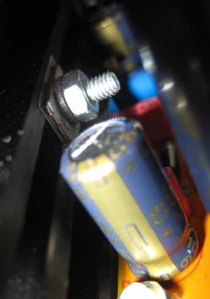
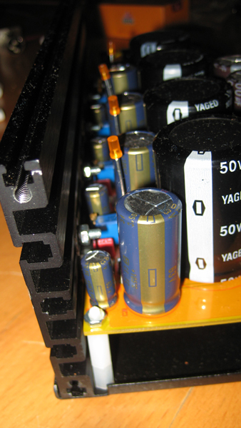
If you want to use the side panel of your PSU case as heat sink for the regs, don't solder the big capacitors before you've done the reg mounting.
First solder the regs, drill the 3mm holes for the regs and then solder the caps. Once the big caps are soldered, you don't have good access to the regs.
I found a little workaround for my Modutec case.
IMG_0526.jpg

IMG_0524.jpg
 
okay, PSU PCB is populated, gettin into the high voltage side of things now.....

I guess for 220V operation I need to connect one yellow to one white cable on the primary side of the mains tx, while attaching the remaining yellow and white to 220V mains? this is what it looks like on volker's first picture but it's not very clear.

the green-yellow lead from the transformer connected to the chassis as well as the earth pin on the mains connector - right?

ETA another question, what kind of mains fuse would be appropriate on the primary?

cheers
brio
 
briomusic said:
okay, PSU PCB is populated, gettin into the high voltage side of things now.....
be careful with the mains !!!

briomusic said:
I guess for 220V operation I need to connect one yellow to one white cable on the primary side of the mains tx, while attaching the remaining yellow and white to 220V mains?
yes - and for 115V you parallel both yellow and both white cables

briomusic said:
the green-yellow lead from the transformer connected to the chassis as well as the earth pin on the mains connector - right?
the green-yellow is the screen winding. I don't know which is better, bringing it directly to the IEC or to the star ground?
did both in my life.
and yes, the earth pin of the mains connector has to be connected to the chassis !!!
you see a nice star ground scheme for the PSU in Holgers unit:

511psu.jpg


note there are two ground planes (ground & chassis), constantly separated from the rack up to the PSU, they should only "see" each other at one point: the star ground. like Holger did it!

briomusic said:
ETA another question, what kind of mains fuse would be appropriate on the primary?
it is a 188VA transformer, 188VA / 230V = ~ 0,82A
 
okay making progress (without blowin any fuses or electrocuting anyone :) )

basically I have one rack working, tried a self-built air eq and a commercial API 512c, which both worked fine.

however - there seems to be a problem with 48v phantom power. the 48v rail checks out ok, but on the xlr the voltage 'fades' from 48 to 0 Volt in about 5 seconds after engaging phantom power. any idea why that would be?

this only happens with the back connector, the xlr plug on the front of the 512c unit checks out fine.

i wonder if this is connected to my grounding scheme? but how can I disconnect pin 1 from chassis on the input?

thanks

ETA: solved in order to use phantom pwr on the back input with this particular unit, pin 1 must be connected to ground, a connection to the chassis will not work
brio
 
Back
Top