official GDIY51PSU Help & Support Thread

GroupDIY Audio Forum

Help Support GroupDIY Audio Forum:

This site may earn a commission from merchant affiliate links, including eBay, Amazon, and others.
Now you Know the Force of Jumpers.
But this shouldn't Be, check if your grnd is connected to Chassis in the psu, and if the Chassis pins in the psu Cable are Fine.
 
benlindell

I ordered GBJ1001-FDI-ND from Digi-key.

I don't have the psu board yet but it looks like it will match the offset or the + pin.

JamesW
 
Do you think this one would work?

http://www.mouser.com/ProductDetail/Shindengen/D6SB80-7000/?qs=zt%252brdKEucxAqN2CIq3D2LA%3d%3d
 
It would work.

Any bridge rectifier in that type of casing (and the current rating) will do your job. You may have to bend the legs a bit but that is all.
 
Next step:

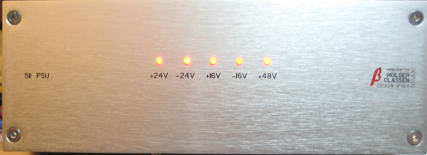
frontled.jpg


;D
 
So I'm a little confused on how many pins on the connector I need. I see there are 2 chassis connections and a ground, are all of these necessary? I can easily find 7 pin connectors, but not so much 8 or 9 pins.
 
benlindell said:
So I'm a little confused on how many pins on the connector I need. I see there are 2 chassis connections and a ground, are all of these necessary? I can easily find 7 pin connectors, but not so much 8 or 9 pins.
one chassis is enough. there is just no 7 pin Molex available, and it would not fit the pitch.
thus I doubled the chassis, but they are connected to the same chassis plane at the backplane and at the PSU.
 
Holger said:
You need a 6 pin connector: 5 different voltages and one for ground/0V.
Chassis goes to the corresponding case (PSU/Rack)
In this case you should connect the chassis ground and 0V together.
I don't trust chassis connections to the rack only, and the rack doesn't have an IEC.
 
[silent:arts] said:
Now you Know the Force of Jumpers.
But this shouldn't Be, check if your grnd is connected to Chassis in the psu, and if the Chassis pins in the psu Cable are Fine.

It shouldnt be, but it is  ::)
I tried, I have continuity from the mains plugs earth pin to any point at any chassis, and thereby also to pin1 of all the input xlrs (which default to chassis regardless of jumper), but I do need to connect pin1 to GND also, using the jumper, if I want the API 512c module to pass 48v phantom power to the back connector - strange stuff indeed. luckily there is a solution.
 
Just thought I throw up a list here.
These are just some parts I am missing for this PSU found at Mouser. You can make your own list but this might help.

Bridge Rect 625-2W01G-E4
Bridge Rect 627-D5SB80-7000
Regulator  595-TL783CKCSE3
8 pin head  538-26-60-4080
1k Trim    81-PV36W102C01B00
0.01uF Cap  581-SR211C103KAR
0.01uF Cap  505-MKS2.01/63/10
100uF Cap  647-UFW1V101MED
1000uF Cap  647-UFW2A102MHD
1000uF Cap  647-UFW1H102MHD
240ohm Res  660-CF1/2C241J
10000uF CAP 647-UFW1H103MRD


Chuck
 
ChuckD said:
Just thought I throw up a list here.
These are just some parts I am missing for this PSU found at Mouser. You can make your own list but this might help.

Bridge Rect 625-2W01G-E4
Bridge Rect 627-D5SB80-7000
Regulator   595-TL783CKCSE3
8 pin head   538-26-60-4080
1k Trim     81-PV36W102C01B00
0.01uF Cap   581-SR211C103KAR
0.01uF Cap   505-MKS2.01/63/10
100uF Cap   647-UFW1V101MED
1000uF Cap   647-UFW2A102MHD
1000uF Cap   647-UFW1H102MHD
240ohm Res   660-CF1/2C241J
10000uF CAP 647-UFW1H103MRD


Chuck

I believe the WIMA on your suggested parts list should be a .1 uF instead of a .01 uF, unless I'm mistaken. Try 505-MKS2.1/63/5 instead. Thanks, your list saved me some time diggin.

::EDIT::

Just noticed that the 5% tolerances are on back order, guess I'll be using 10%s.  505-MKS2.1/63/10
 

Latest posts

Back
Top