one transformer driving two bridges

GroupDIY Audio Forum

Help Support GroupDIY Audio Forum:

This site may earn a commission from merchant affiliate links, including eBay, Amazon, and others.
I might be wrong, but I think that the zener + transistor thing will have nicer performance than the very common 78xx and LM317 regulators used on most DIY projects we see here.
 
[quote author="rafafredd"]I might be wrong, but I think that the zener + transistor thing will have nicer performance than the very common 78xx and LM317 regulators used on most DIY projects we see here.[/quote]
I totally agree, which is why I wanted to layout a board like this. I've had too much trouble with 317s and the 78xx is just too noisy for some apps.
 
[quote author="Family Hoof"][quote author="rafafredd"]I might be wrong, but I think that the zener + transistor thing will have nicer performance than the very common 78xx and LM317 regulators used on most DIY projects we see here.[/quote]
I totally agree, which is why I wanted to layout a board like this. I've had too much trouble with 317s and the 78xx is just too noisy for some apps.[/quote]

Performance is a wide-open term. There are parameters like line regulation, load regulation, ripple rejection, noise, dynamics of the first two, short-circuit protection, input-output differential, and so on.

But at least these circuits are simple enough to breadboard before spending the time doing a board layout.
 
One point of mention that Bcarso points out (i think, i read it quickly..) I was looking to regulate without the use of darlington/emitter-follower arrays. I only did some quick looking but i believe there are plenty of devices that should work well here.

Bcarso and I were talking about the SiC diodes.. I think this would be a perfect place to use them!

As for the R in series with the bases.. what do you suggest for size? usually i see 100 or 1k for base/gate series Rs.

if anyone even thinks of using a TL431 in place of a zener, I will personally slap you. I have had nothing but issues with them unless you like building crappy unbranded chinese switchers.. :green:

Bcarso, in the situation where the output V falls slower than the input and you get a reversed biased BJT, would you suggest a (fast)diode between the emitters and the output caps to isolate them from the caps? I have not simulated or tried this yet, it's just a quick idea..
 
[quote author="Svart"]One point of mention that Bcarso points out (i think, i read it quickly..) I was looking to regulate without the use of darlington/emitter-follower arrays. I only did some quick looking but i believe there are plenty of devices that should work well here.

Bcarso and I were talking about the SiC diodes.. I think this would be a perfect place to use them!

As for the R in series with the bases.. what do you suggest for size? usually i see 100 or 1k for base/gate series Rs.

if anyone even thinks of using a TL431 in place of a zener, I will personally slap you. I have had nothing but issues with them unless you like building crappy unbranded chinese switchers.. :green:

Bcarso, in the situation where the output V falls slower than the input and you get a reversed biased BJT, would you suggest a (fast)diode between the emitters and the output caps to isolate them from the caps? I have not simulated or tried this yet, it's just a quick idea..[/quote]

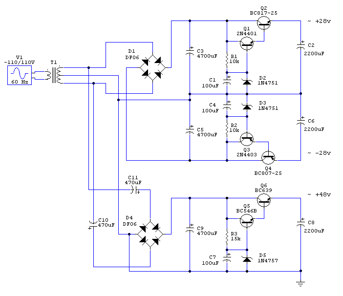
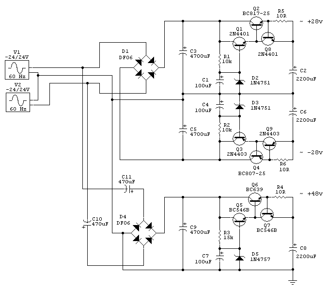
For the series R it will depend on the size of the device and hence the rating. It is more of a pulse energy issue which is mostly undiscussed in datasheets, and this in turn will depend on how large the zener (or other reg.) cap is. Ballpark I would say is 50-100 ohms for a MJE172/182 device and a 220-470uF cap.

Don't know what your problems have been with 431's, although they do get abused in the standard offline switcher when paired with the simple optoisolator. I have used literally millions of them in a more benign environment, as a voltage reference with a good long tau R-C filter afterwards feeding an error amp, and had no problems. They are, like most bandgap-based references, somewhat noisy and prone to oscillation depending on current and capacitive loading. The manufacturers tell you about this, and at least the reputable ones are pretty accurate about the behavior. But they are being made by all and sundry now and getting down to about 6 cents in quantity, so who knows what horrors lurk.

There are ways to make quieter bandgap refs out of discrete Q's. Zener noise iirc is all over the map but I haven't looked at them recently enough to be quantitative. When I needed a really quiet ref I used a JFET CCS biased at the ~zero-tempco point and developed a voltage across a resistor, and buffered this with a good amp. The whole shooting match was oven-stabilized---clearly not too practical for everyday use! But it did way outperform anything that was out there, and I suspect it would hold its own today as well.

Back to the e-follower regs at hand: to protect the potentially reverse-biased junctions without other losses the best thing is to place the diodes across rather than in series. They don't have to be especially fast. They shouldn't be any larger than they have to be since they are capacitive and this can only slow things down in normal operation---but these are small effects.
 
excellent! it's always good to be able to ask someone much wiser!

I had thought about the JFET current source and turn it into a Vreference.. would you say that it IS or ISN'T worth the time?
 
[quote author="Svart"]..snip...
I had thought about the JFET current source and turn it into a Vreference.. would you say that it IS or ISN'T worth the time?[/quote]

The JFET approach requires that one determine the zero tempco point for the part, if you want it to be low drift. If this point is at an inconveniently low current then you need a different part. Since FETs vary a lot from sample to sample it is not a practical approach for manufacturing imo, but for hand-built stuff should be fine.

The longer-channel devices seem to be best for having the zero tempco at a usuable amount of drain current---it looks like the Tosh. 2SK246 is a pretty decent candidate. The nominal Vgs for this region is typically about 0.6-0.7 volts more "on" than the pinchoff voltage, but I spent hours adjusting source R's and heating and cooling parts to find the best region for a given part.

A single FET is not very good for line rejection by itself, so some preregulation is advised. A cascode config. with a higher pinchoff FET might be enough, or the regulator can incorporate the FET in bootstrapped fashion.

Some low pinchoff FETs like the 2SK170 may not work at all---the zero tempco point can actually occur with forward bias on the gate :shock: But this also means that some samples may be just right at Idss (zero Vgs) which would be convenient.

Also, the tempco is only zero at a given temp and isn't perfect above and below---but for our typical environments it can be pretty decent.
 
Bcarso translation: 'it's not worth the time'

:green:

I still find it interesting though!

the TL431.. It's not a *bad* part per se, but I have found a few of them to act slightly *different* from each other for the same part.. this makes a drop in solution a little problematic.. for people who use them in DIY and can fiddle with biasing by hand then there is no problem at all, but for companies wishing for accuracy AND precision then that is another problem altogether.. Most switching PSUs that use them use them in a "good enough" situation where output regulation isn't of super-great importance. however in our little DIY linear PSU, i think we could do much better than just "good enough".

:thumb:
 
It works! same solution as in a F*ocusrite ISA430

It seems that it doesn´t???

Argh! I just tested this:

JLM_OLD_PSU_moded_4.gif


And guess what? No negative output... :? Just like PRR said in his first post. :oops:

I can´t see why this works thought, and it does, as I did used this one once:

kps1sch.gif


Or this JLM PSU...

http://www.jlmaudio.com/JLM%20ACDC%20Schematic.pdf

What is it that I can´t see??? What´s your secret keith???

I must say I´m very confused. :?: :sad:

Will I have to buy another power transformer just for the phantom?
 
[quote author="rafafredd"]
And guess what? No negative output... :? Just like PRR said in his first post. :oops: [/quote]
PRR was reffering to your first design (without center tap).
What is it that I can´t see???
Did you check your wiring and components for errors? Your last sch looks good to me.

Regards,
Milan
 
For non-automotive applications, I rather like the LM78xx and LM79xx regulators, but I always use a lot of capacitance on the output to swamp the noise out, and if you do that they have very good regulation and low noise output. I often put 470uF of output capacitance, along with the reverse protection diodes recommended by the manufacturer.

I got into the habit of oversizing the output capacitors because in my day job (automotives), low dropout regulators are what you need to use, and they require typically greater than 10uF of output capacitance just to stay marginally stable, and often the manufacturer recommends 33uF to 100uF.

For engine management controllers, LM9072 or TLE6368 are what I use most often, but the LM2931 is sort of a workhorse if I just need a simple regulator.

rafafredd's second schematic (with the bridge and two capacitors) appears to be actually two voltage doublers in parallel. C3 is one phase and charges during top (of transformer) negative and dumps into C5 on top positive. C4 is the other phase and charges during bottom negative, and dumps into C5 during bottom positive. That's a nice design - half the ripple of a voltage doubler, actually.

For phantom, I often will place a large capacitor (I use around 100uF or so) between ADJ on the LM317 and ground, but you need to be a bit careful while doing this. I use the LM317HVT, because during power-up the regulator will be dropping higher than 40 volts briefly, and the application notes with the chip show you what protection diodes you need to add. But I've found that this really reduces the hum and noise on the phantom 48 volt line.

Just my humble opinion way too early in the morning.
 
> guess what? No negative output... Just like PRR said in his first post.

About your first plan.

I can't take credit for JLM_OLD_PSU_moded_4.gif not working.

Don't even think about the regulators until you get the raw DC supply working.

It looks fine. Assuming a 24V-0-24V (48VCT) transformer, center tap connected to Common, no/light load, we get:

C3 = +35V
C5 = -35V
C9 = +70V

If you are not getting these numbers, something is not wired as drawn.

Any of these transistors will die an instant death when shorted. They could even die at switch-on due to the huge charging current in C2 C6 C8. Which is another reason not to look at regulators until you get happy voltage at C3 C5 C9.
 
Yeah, maybe it´s just a dead negative transistor. I´ll swap transistors. Unfortunatly it would be very difficult to redo the plain without the regulator... It´s actually in a veroboard full of components, but if it doesn´t work after transistor swap, I´ll try to do it.
 
Update...

Swaped transistors and it does work just fine now... and guess what???...It´s quieter than three pin regulators like LM317 and 78xx series. Just as planned.

I´ve probably shorted the output somehow in the first test, as there was a bad transistor in the negative rail... This is my try on a short-circuit proof version. I still wanna keep it simple and good performance, so if this simple one transistor short circuit protection works, then I´m done. This is my all-time solidstate mic pre PSU. Just one trafo, quiet, low parts count, can be scaled-moded easily up and down for almost any current needs. What elese should I want?

Here it is:

discreet_PSU_protected_5.gif
 
> it would be very difficult to redo the plain without the regulator... It´s actually in a veroboard

So? What ya should do is: wire transformer, rectifiers, first caps (lot of them in the 70V supply), be sure commons are wired, stop, apply wall power (stand back), and see what happens. Any linear regulated supply starts with an unregulated supply, which must work or there is no point fooling with regulators.

Yeah, if all is well the voltage will be a bit high, but if all is not well, better to find the problem and fix it.

> my try on a short-circuit proof version.

Q1 Q3 will die instantly. Maybe at start-up. Their current is unlimited(*). See why?

(*) Well, OK, they may act as 1 ohm resistors, Q8 Q8 too. With 30V input that is "only" 15 Amps, and a little 225 Watts of heat.
 
The circuit below should work with current limiting and a lot less smoke than the circuit back up the page a bit.
discreet_PSU_protected_5_JLM_Mod.gif

But 2 of the right current fuses or ployswitches in series with each transformer secondary would work just as well.
 
So? What ya should do is: wire transformer, rectifiers, first caps (lot of them in the 70V supply), be sure commons are wired, stop, apply wall power (stand back), and see what happens. Any linear regulated supply starts with an unregulated supply, which must work or there is no point fooling with regulators.
Yes, I did it before swaping transistors and it´s all well. The regulators works nicely now. I just wanted to try a short circuit protection mod because I hate to unsolder transistors, and I hate when they go PAF!

The circuit below should work with current limiting and a lot less smoke than the circuit back up the page a bit.

Thanks for correcting the circuit, JLM. I´ll try it in my next version, as this Veroboard version is already very crowded.
 
Sorry to resurrect this topic.
If I need 18V instead of 28 would it be enough to change zeners only (1N4746 instead of 1N4751) or should I tweak transistors as well?
 
Thanks for the answer, Joe.
There're also those small surface mount transistors (BC817-25/BC807-25). Are there any thru-hole sustitutes and are there any specific recomendations for those transistors?

EDIT: I've just found the suggested replacements for SMDs:
BC327-25 for BC807-25
BC337-25 for BC817-25
I think they'll work. BTW why do people use SMDs here and thru hole in other places of this circuit?
 

Latest posts

Back
Top