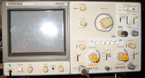
> COS5020. Is this the difference between sine and COS?
No.
That's a mathematic distinction about what part of the cycle you call "start". SIN and COS are the same thing in a real world where we pick a start-point for arbitrary convenience. "COS" probably stands for "Cheap OscilloScope"... ah, Kikusui product numbers run like AVM13=AC voltMeter, DME1400=Digital multiMEter, PAB13= Power supply, FC01120= Frequency COunter. So maybe "COS" is "Cathode ray OscilloScope" (opposed to LCD 'scopes), whatever.
And how could they sell a box marked SIN? My purchasing dept would see "SIN69 - 1ea @ $399.98" and think it was a joke.
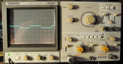
> one cycle per 82.5ms with wall signal. I need to figure out how to calculate this in to hertz.
60 cycles per second is 1/60 of a second per cycle. 1/60 is 0.016,666 seconds, 16.66 milliSeconds.
One half-cycle in 8.3mS is correct. Set sweep to 1mS/div and see if you get a bit more than half a complete wave.
PLEASE do this with a 120V:12V transformer, NOT right off that wall-cord.
Or just put your un-grounded finger on the probe tip. Any indoor workroom will throw a large fraction of a Volt of stray 60Hz buzz onto an un-grounded body. It will have a lot of "garbage", because stray line-spikes couple better than low 60Hz tone; but you can usually sort-out the basic 60Hz roundy wave.
5%-50% of ex-school-lab 'scopes will be defective some way, depending how sharp the students were about detecting problems (they have less practical experience than you) and how energetic the lab tech was in fixing the old 'scopes after new ones were budgeted.
For $50, the going rate for a used-working 5020, you should ask for explanation or a swop. For free, you can only throw yourself on your friend's mercy.
> the input for the probes reads 25pf and the probes read 14pf...could this be my problem?
No. A serious mis-match will round-down/spike-up high frequency shapes. But no effect on a 9V battery. And probes invariably have a range of adjustment for different inputs. That's why they give you a known-sharp square-wave. Aside from the known voltage, you know the corners are crisp. Verify with 1X probe. Then put probe in X10 mode (and bring up V/div). If the "square" is round-shoulder or spike-corner, use a fine screwdriver in the probe and you will get a different shape. When you get a best-possible square, the probe is matched to that cable and input. You won't have to re-adjust if you use that probe on the other input, but you will have to adjust if you use that probe on another 'scope, or if you do much-much finer work than a $free 'scope should be expected to do.