Overkill tube pre/EQ called Drive-1. Maintenance update.

GroupDIY Audio Forum

Help Support GroupDIY Audio Forum:

This site may earn a commission from merchant affiliate links, including eBay, Amazon, and others.
EEMO1 said:
nice!!!

pics-max-14974-327602-chevrolet-impala-1959-on-boyd-coddington.jpg

holy sh*t! was that a guess or did I actually tell you at some point? Below is the exact image I used for color grading.

index.php


I can never have a car like that. But at least I can have an amp to match.


To answer the other questions. Yes the panel is two layers. Bottom is aluminum painted green. The fonts and graphics are actually a transparent sticker, so no silk screening here. The top panel is also aluminum, but covered with leather. Stretched tight on the corners with contact glue, and most people (including wife) thought it was wood.

The front panel sticker design was mostly stolen from this classic: http://www.grouseguitars.com/sold/moodyblonde.htm
I also wanted to use that "fridge magnet" style wing logo (slightly modified with my own name), but I don't know where I could have them made.
 

Attachments

  • coddington-colormatch.jpg
    coddington-colormatch.jpg
    81.7 KB
Kingston said:
...............
The front panel sticker design was mostly stolen from this classic: http://www.grouseguitars.com/sold/moodyblonde.htm
........

The word is "borrowed". Don't do disservice to yourself.

Great stuff. Well done.

 
I'm down to the last tweaks now and just about to wrap up the project.

See the first post of this thread for updated, and hopefully final schematic. But also check out the first PCB's uploaded for public viewing.

There is one strange issue that I'm still troubleshooting, and it only happens on right channel on this dual channel unit. They have both been built and measured (voltages/capacitance/resistances) identical. If I swap the PCB's and/or all pots and switches around, the problem still happens on the right channel!  :eek:

See the latest schematic: http://www.michaelkingston.fi/files/Drive-1_schematic_rev1.9.pdf

Basically, If I have the full volume at output stage VR4, everything is fine. Step down volume some 3dB, and the channel starts to very slowly motorboating the volume. Other channel is always fine. The motorboating speed is somehow dependant on the amount of bass of test material. If I turn down volume further, the motorboat speeds up turning into a kind of warbling distortion. Turn down even more and it disappears.

This is with the cathode bypass cap switched out of the circuit (SW3B). It doesn't happen with the cathode bypass cap.

Now here's the strangest thing, if I measure voltage between ground (B-) and output tube V3B grid, the motorboating stops completely! Everything works and measures perfectly! It stops whether or not I have the grid stopper (GS) or R21 grid shunt installed. Just touch ground and grid with multimeter and the problem is gone.

What the heck does the multimeter do to make it stop?

Please help! I don't really feel like installing this in a rack with a whole multimeter inside.  ???

Also, oscilloscope doesn't find anything strange either. Or I can't think any way I could use it to help find the culprit. Soon as I touch the grid with the oscilloscope, the problem is gone just the same as with the multimeter.

[edit]

I only need to actually touch the grid with the multimeter probe! I don't even need to touch the other side to anything at all, and the problem is gone!

AAAARRRRGGHH! who the heck are these magical spirit energies messing with my build?!  :-\
 
would installing a small (100pF - or a couple hundreds pF's) cap between V3B grid and cathode help?

(or alternatively, between grid and ground)
 
That did the trick. 100pF wouldn't yet help, but 270pF did, between grid and cathode. Between grid and ground caused another type of strangeness.

Thank you. No idea what was happening there in the first place. What do you think was going wrong?

That brings this project to completion. Whoever is interested, do what you will with the schematics and PCB etching files.
 
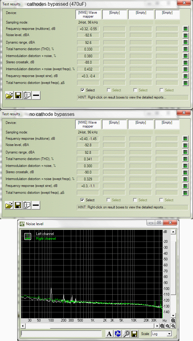
A suite of specs.

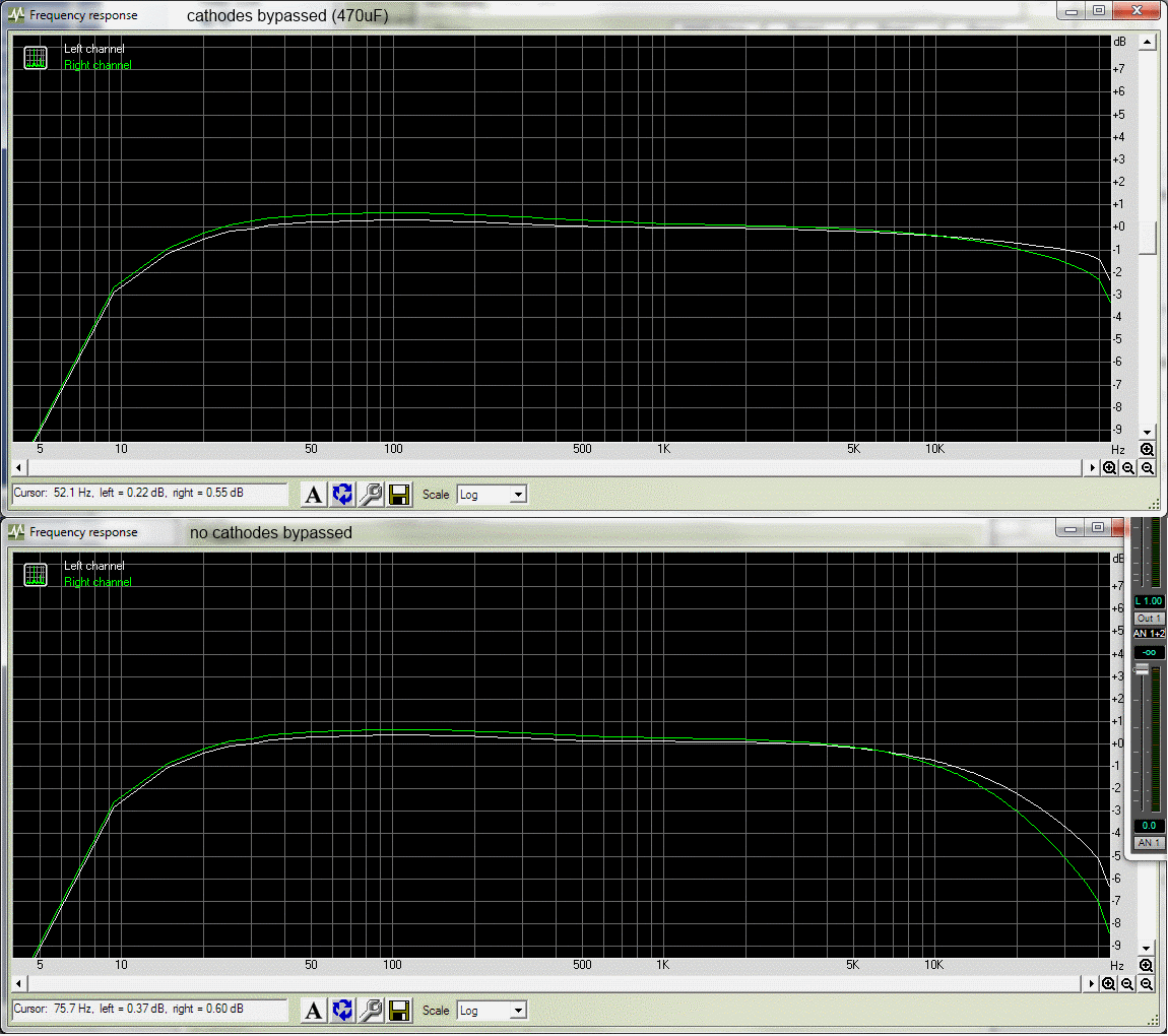
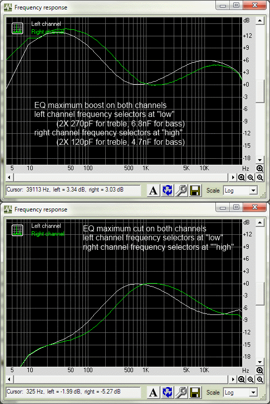
It should be mentioned the frequency responses of the EQ's of both channels match to perfection. The slight deviation of high frequency responses seen on right channel come from the 270pF grid-cathode fix as discussed above. Left channel worked fine without it. All tests were done with Drive-1 gain set to unity and input pad engaged. Measurement device was RME HDSP at 96khz.

This is what would call a mastering starting point setting, with minimum overdrive possible from the unit. But you can go crazy with overdrive, there's gain to spare.

Drive-1-specs.png

Drive-1-freq-response-unity-gain.png

Drive-1-shapes-of-EQ-responses.png
 
ok, cool ... gdiy remote-reiki healing sessions...

I think that tube went into self-oscillations when the impedance that the grid was seeing (from the potentiometer) went temporarily higher (when you turned the gain slightly down).
 
The lessons learned section.

Caps in the PSU don't have to be anywhere near 100uF. 22uF is just fine since there's so many (too many) stages of RC and finally the shunt/dumb regulators. Specs won't suffer. In the amp section the RC caps can be lower than 22uF as well. Heck, try 1uF and the thing will become much bouncier and more interactive. Probably sounds better too. The second B+ regulator is not needed either. Just feed all amp sections from the first and there's actually more headroom on the first stages of the amp. I put the second regulator there with another future project in mind. The choke optioned in the schematic is totally pointless. I didn't use any. This PSU PCB is quite universal for other tube projects by the way. Can easily power a bad-ass overkill vari-mu project that I will design next.

310V at the output stage is generous. Too much so. When playing with the plate starve, don't trust the "2k8" penciled in the schematic. Needs to drop a lot to hear any significant difference. I think I ended up dropping like 150V that made a difference (more and rougher distortion). The plate starve resistor needs to handle a lot of watts. The amp eats something like 70mA for two channels. A big dumb resistor. Don't use any children's switches/relays there either. There's like 400V at that point. I used a digikey part 306-1195-ND but it doesn't seem to be available anymore.

All values in the schematic are very non-critical. Can deviate even 20% from what I wrote probably won't hear a difference. Tubes are cool that way.
 
Hi !

Would the TIP50 + zener diodes regulator circuit be beefy enough to power a small guitar amp with two EL84 output tubes ? I'm thinking to convert my Fender Hot Rod Deluxe (2x 6L6GT P-P, 40W) to a Vox AC15 (2x EL84 P-P, 15W), but I need to drop some voltage on the PSU not to fry the EL84. In the original Vox circuit the plate voltage is already about 374V (300-0-300 trafo), far above the 300V limit on the tube's datasheet, but I'm afraid 455V (325 - 0 - 325 trafo) might be too much for those poor babys ;) Looking at the TIP50 datasheet it seems that it could handle it (120mA, and a voltage drop of about 80V, that is to say about 10W), but I have no experience with those high voltage circuits so I prefer being careful and ask...

By the way, this tube pre looks awesome ! I'd love to hear some soundfiles, and with guitar as well !

Best regards.

Eric
 
Forget TIP50, see what it says next to it in the schematic:

MJE18004G.
POWER TRANSISTOR
5.0A
1000V
75W

Just make sure to use a big heatsink. It will work fine. But it's not a good idea to use regulated PSU's for guitar amps in my opinion. They are too linear and will make the sound boring and perhaps unresponsive to playing dynamics. With guitar amps and perhaps tube power amps in general (and sometimes even mic preamps) you actually want the B+ voltage to sag with high loads. But don't take it from me and build away, it should be a cheap experiment.

For dropping voltage in that amp of yours you should really only need a resistor and a cap. Or maybe just a resistor to replace the existing B+ CRC resistor that will certainly be there already.
 
Thanx for your answer, Kingston !

My first idea was actually to add a series resistance but after computing the value needed to get a sufficient drop it was about 820R, and I'm afraid that would give me too much PSU sag... My plan was to drop some voltage with the regulator and add a serie resistor to simulate the sag of a tube rectifier (about 2x 230R for a EZ81 at 350V).
I also had this idea : using a regulator could allow me to reduce the power of the output stage by lowering B+ ! I know those tube sound better when fed with high voltage, but that might be a better solution than power breaker, etc.
Best regards.
Eric
 
ricothetroll said:
My first idea was actually to add a series resistance but after computing the value needed to get a sufficient drop it was about 820R, and I'm afraid that would give me too much PSU sag... My plan was to drop some voltage with the regulator and add a serie resistor to simulate the sag of a tube rectifier (about 2x 230R for a EZ81 at 350V).
100R seems to be a popular value for that kind of power amp.


ricothetroll said:
I also had this idea : using a regulator could allow me to reduce the power of the output stage by lowering B+ ! I know those tube sound better when fed with high voltage, but that might be a better solution than power breaker, etc.
It is a good solution, just don't forget to compensate for the bigger power in the transistor with a bigger heatsink. Of course that only works for cathode biased amps.

Open your own thread maybe? ;)
 
Hi Volker,
Thanx for your answer !
Sorry for being off topic, I'll open another thread if I have some other questions.
Best regards !
Eric
 
I'm considering building the Drive-1 pre.
I've studied the schematic and I've got a couple of questions. Maybe some folks here can help me figuring them out.

First, the PSU heaters filter bank caps values are very large. I've browsed through several PSU circuits for tube gear and I've never found heater regulater filters to be that large. Is there any special purpose for that?

Second, the heaters supply is floated to the B+. What's the benefit of this?

Third, is there any reason (sound wise) to make a tube regulated PSU instead of solid state? I remember Winston O'B speaking regarding that subject - that some semiconductors throw out a lot of hash and that we're essentially listening to the PSU. Any thoughts on that matter are highly appreciated.

Thanks!
 

Latest posts

Back
Top