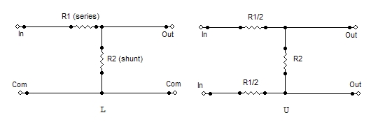
3nity Well-known member Joined Dec 30, 2005 Messages 3,637 Location MTL, CANADA Jun 22, 2009 #1 would a schem like this work as a pad on an unbalacned line?? Thanks..
R rodabod Well-known member Joined May 12, 2005 Messages 2,896 Location London Jun 22, 2009 #2 The L-pad on the left, yes. It's just a voltage divider.
3nity Well-known member Joined Dec 30, 2005 Messages 3,637 Location MTL, CANADA Jun 23, 2009 #3 I'm still wondering hot to make its switchable!! thanks..
Kingston Well-known member Joined Nov 1, 2005 Messages 3,716 Location Helsinki, Finland Jun 23, 2009 #4 a simple on-on (SPDT) switch will do. 1. disconnect R2 from "Out" and R1. 2. One end of the SPDT switch to "In", other end to the now disconnected R2. middle of the switch goes to out/R1.
a simple on-on (SPDT) switch will do. 1. disconnect R2 from "Out" and R1. 2. One end of the SPDT switch to "In", other end to the now disconnected R2. middle of the switch goes to out/R1.
3nity Well-known member Joined Dec 30, 2005 Messages 3,637 Location MTL, CANADA Jun 23, 2009 #5 this means R1 will always be on the circuit? thanks..
R rodabod Well-known member Joined May 12, 2005 Messages 2,896 Location London Jun 23, 2009 #6 3nity said: this means R1 will always be on the circuit? Click to expand... He's skipping R1 in the first switch position. It is left open-circuit.
3nity said: this means R1 will always be on the circuit? Click to expand... He's skipping R1 in the first switch position. It is left open-circuit.
JPK Well-known member Joined Dec 15, 2004 Messages 209 Location Auch, France Jun 23, 2009 #7 IN--+--/////--+--OUT | | o | o------+ o / | / / / / | _ GND I hope this is clear enough.
3nity Well-known member Joined Dec 30, 2005 Messages 3,637 Location MTL, CANADA Jun 23, 2009 #8 Tres clair merci beaucoup! Thanks to all! its very clear!