Parallel Signal Path for VCA Compressors (eg S S L)

GroupDIY Audio Forum

Help Support GroupDIY Audio Forum:

This site may earn a commission from merchant affiliate links, including eBay, Amazon, and others.

matthias

Well-known member
Joined
Jun 4, 2004
Messages
768
Location
germany / frankfurt
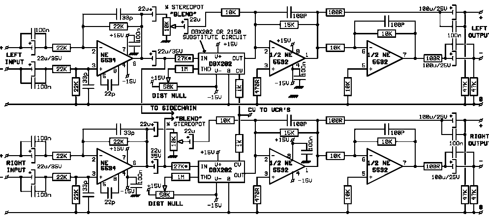
one of my next projects will be a vca compressor like the old dbx boxes and an improved version of the s s l compressor.

for both units I'd like to implement a feature that allows to mix in some of the dry signal.

my first design attempt is this:

vca-par.gif


regarding this I have some quesitions:

r5 should be a level control (from -inf to 0) for the (dry) input signal.

1) Can I leave out R7 and R6 or if not, how do I determine the value?

2) in case of R5, what would be better here, only a series (variable) resistor leading to the neg. input of OP2 or like in the schematic an attenuator to gnd.

3) can OP2 also be an non-inverting opamp or would this cause phase problems with the output signal of OP1

4) how should I determine the value of R5


thanks,
mat
 
As drawn, you're missing the input resistor to your inverting amp, or you're 20k needs to be after the pot. Also, the signals will be out of phase at the output. Instead of the inverting buffer, you can run the summing resistor directly to the node of the output amp.

Instead of the inverting amp, How about running your pot output into the non-inverting input of your output amp (i.e. differential in)?
 
@ crusty: thanks for your help..

here's my try on the differential thing..
but I don't know, if this will work

vca-par-2.gif


I marked the point at the inv-buffer after the vca as "TP-1"
is the signal ther in phase or inverted??


thanks,
mat
 
You are back in phase with the input there.

I was thinking more like this: http://groupdiy.twin-x.com/albums/userpics/10071/BLEND.TSC_-_.pdf
 
A few points:

My reading of the THAT VCA data sheets is that the devices are non-inverting, i.e. positive current in produces positive current out. This means that your parallel path must be non-inverting if you want to mix wet and dry and preserve the phase. The second schematic you posted has the wrong number of inversions between wet and dry paths.

You should not have the dry gain control in the input path of a virtual earth amplifier. The amplifier will see the sum of the input resistor and the parallel combination of the resistances from the pot wiper to each end of the pot. This varies as you adjust the pot, so the gain curve is not linear (or log if the pot is log). Both your original circuit and the revised one have this problem. Much better to buffer the pot with a non-inverting amplifier, which has a high impedance input.

You are also relying on the circuit being driven from a zero ohm source. Again, you should have a buffer here so the resistance seen by the VCA input is constant.

The VCA output amplifier will require a 15pF or 22pF capacitor from its output to its inverting input to maintain stability because of the output capacitance of the VCA.

It's quite OK to use resistive summing in this type of application - you don't need a differential amplifier. With a little care, you can sum at the input of the op amp that receives the VCA current output. So the signal chain would be: input -> voltage follower -> top of pot to ground and also via 20K to VCA input. Pot wiper -> voltage follower whose output goes via 20K to the VCA output and the SJ of the output amplifier. That's all you need, unless you need non-inversion through the unit, when another inverter is needed on the output or you change the first VF into an inverter, giving the circuit a low input impedance.

As an alternative configuration, you could be enterprising and string your wet/dry mix pot across the outputs of the VCA output amplifier and an inverter in the dry path. This would turn the control into a "wipe" between wet and dry, if that janitorial effect is what you are after.
 
@ crusty: if I put the pot in front of the 20k resistor it also pulls down the signa that goes into the vca.

I want the vca signal constant and the parallel dry signal should be variable.

@boswell: the input buffer and stability caps are left out to keep it simple.

the current output of the vca is non inverting,
but it is connected to the input of the inverting amp...
so does the amp invert the signal, or it it only a buffer and keeps the pos. phase??
 
the current output of the vca is non inverting,
but it is connected to the input of the inverting amp...
so does the amp invert the signal, or it it only a buffer and keeps the pos. phase??
The amp output will be phase-inverted with respect to the VCA input.

Just buffer the dry pot and sum at the VCA output. Put another inverter on the final output if you need zero phase shift through the module.
 
thank you... then it should look like this:

vca-par-3.gif


voltage follower whose output goes via 20K to the VCA output and the SJ of the output amplifier.

what do you mean by "SJ"


I first thought about a "wet/dry" control, but the gain coiming from the vca always changes the wet/dry ratio, so I think a simple "dry-mix-control" would be better here..


mat
 
crusty: if I put the pot in front of the 20k resistor it also pulls down the signa that goes into the vca.

It will load it, somewhat, but never more than the overall value of the pot. You need a i/v resistor in front of your inverting amp.


My reading of the THAT VCA data sheets is that the devices are non-inverting, i.e. positive current in produces positive current out.

Interesting, I didn't know that. I only use the 4301, who's vca inverts input to output. I wonder if they changed it so their minimal-part applications would be in phase input/output?

Mat. try it without the buffer (op4), it should work fine.
 
Matt,

Loose OP4 - there is no longer any use for it in:

http://i5.photobucket.com/albums/y156/mm303/vca-par-3.gif

Maybe add a 10uF in series with the 20K to cancel DC offset errors between in and out of VCA.

Jakob E.
 
I already tried it without a buffer, but it doesn't work properly.
when I increase the gain of the vca the signal flows backwards through the resistors to the vca input ... and when the input is higher, the compression increases.

@crusty: the i/v resistor of the inverting amp is the 20k before the vca
(that's the way how it is done in the datasheet)

but is there a way to determine the value of the pot (r10)


thanks,
mat
 
Jakob,
I can confirm what Matthias said, it will not work that way.
Last year I experimented with parallel compression with SSL and tried various methods.

You posted this variant:
SSL_PAR_feed.gif


It was in this thread:
http://www.groupdiy.com/index.php?topic=868&postdays=0&postorder=asc&start=15

It will not work this way. It needs a buffer.
I found the best way is to use a buffer for the dry signal, and to sum the dry and compressed signals into a potentiometer that behaves like a panorama pot. At one end it is clean, at mid is 50/50% and at the other end is only compressed. This way you have a better control of the dry/wet ratio, and you have aproximatelly a constant mixed level (no need to lower makeup gain to compensate the increase of level when you ad the dry signal) .
I think this is a much more versatile solution than a pot that can only ad some dry signal to the compressed one.

chrissugar
 
what do you mean by "SJ"
SJ is the summing junction of the output op amp, in this case.

You got the diagram exactly right. You do need OP4 to buffer the dry pot R10. The value of R10 is not important - 20K would be a good choice. It has to be large enough so that it does not load the input buffer unduly, but small enough that OP4's bias current flowing through the variation of resistance over the range of the pot does not cause appreciable d.c. changes at the output of OP4. This will, of course, depend on the type of amplifier chosen for OP4.
I only use the 4301, who's vca inverts input to output.
That's because the 4301 has the output amplifier built-in. Think of the 2181 as a voltage-controlled input resistor to the SJ of an inverting opamp.
 
keef did a pretty goodlookin one in this thread -

http://www.groupdiy.com/index.php?topic=8360&highlight=crush+blend

his was a stand alone unit for using with any compressor but you could just stick it straight inside your comp as-is.

dual 10k lins are easy to get too if you want it stereo.
 
Hi Chrissugar,

Thanks for the clarification.

But the problem is strange indeed - the circuits, both the VCA and the resistor from the mix-in pot both looks into a virtual-ground mix amplifier, so (in theory) there should be no need for a buffer at all.

Any idea about what goes wrong here?

Jakob E.
 
Yes, it does seem odd. I stipulated the buffer purely on the grounds of (a) linearising the dry pot and (b) presenting a constant resistance to the summing amp, so its noise gain did not change over the range of pot operation.

There is a difference between a traditional resistor mix into a summing junction and the summing of current-out devices such as the THAT 2181. The current-out devices have a very high effective output resistance, and so contribute little to the noise gain of the summing amp. Years ago I designed a mixer with a large number of channels that used transconductance amplifiers at the channel outputs (volts in - current out). This meant that the mix amps ran effectively at unity noise gain, circumventing the problem that is getting a lot of airing in another thread at the moment about noise levels of multi-channel mixers.

But in the present VCA wet/dry case, perhaps both Matthias and Chrissugar could indicate more exactly what went wrong in their respective circuits when tried without the buffers? It would be instructive to nail this one.
 
In my experiment when I started to add the dry signal, it started to behave very strangely. The higher the dry level, the stranger the pumping. It was worse than the compressed signal alone. I had the impression that it was some kind of phase related problem because the pumping was not exactly the same on the whole spectrum. Very strange. And the strangest behaviour was at max dry level. Isn't it possible to be related to some kind of positive feedback? Just a thought.

chrissugar
 
That's because the 4301 has the output amplifier built-in. Think of the 2181 as a voltage-controlled input resistor to the SJ of an inverting opamp.

Actually, the VCA output is available, inverted, and I have summed signals there before without weirdness; which leads me to believe it's a different beast than the 218X stuff. I think I'll email That Corp...
 

Latest posts

Back
Top