Lumberjack
Member
I own a Peavey Classic Series 120 mono poweramp that doesn't have any resonance or presence controls. There is a stereo version of this poweramp, the classic series 120/120, which does have resonance and presence along with input level on the front instead of the back. If you've never heard of this poweramp, think of it as the predecessor to the 5150 poweramp.
I assumed that the two circuits are identical, one just being two mono blocks in parallel, and I thought that I could just insert the presence/resonance circuit 1:1 into my own mono poweramp, but after inserting the little circuit into the poweramp, I noticed that the resonance control acts very weird when set to the lowest 20% or so of the potentiometer range. There's no sound and the powertubes seem to be overwhelmed as they start to overheat drastically.
How is this possible? Why doesn't the stereo version of the circuit work in the mono version when the two designs are 99% the same. There are some differences near the diode bridge, like added capacitors, different values etc., but that's not the EQ circuit anyway and shouldn't influence the behavior of the resonance control.
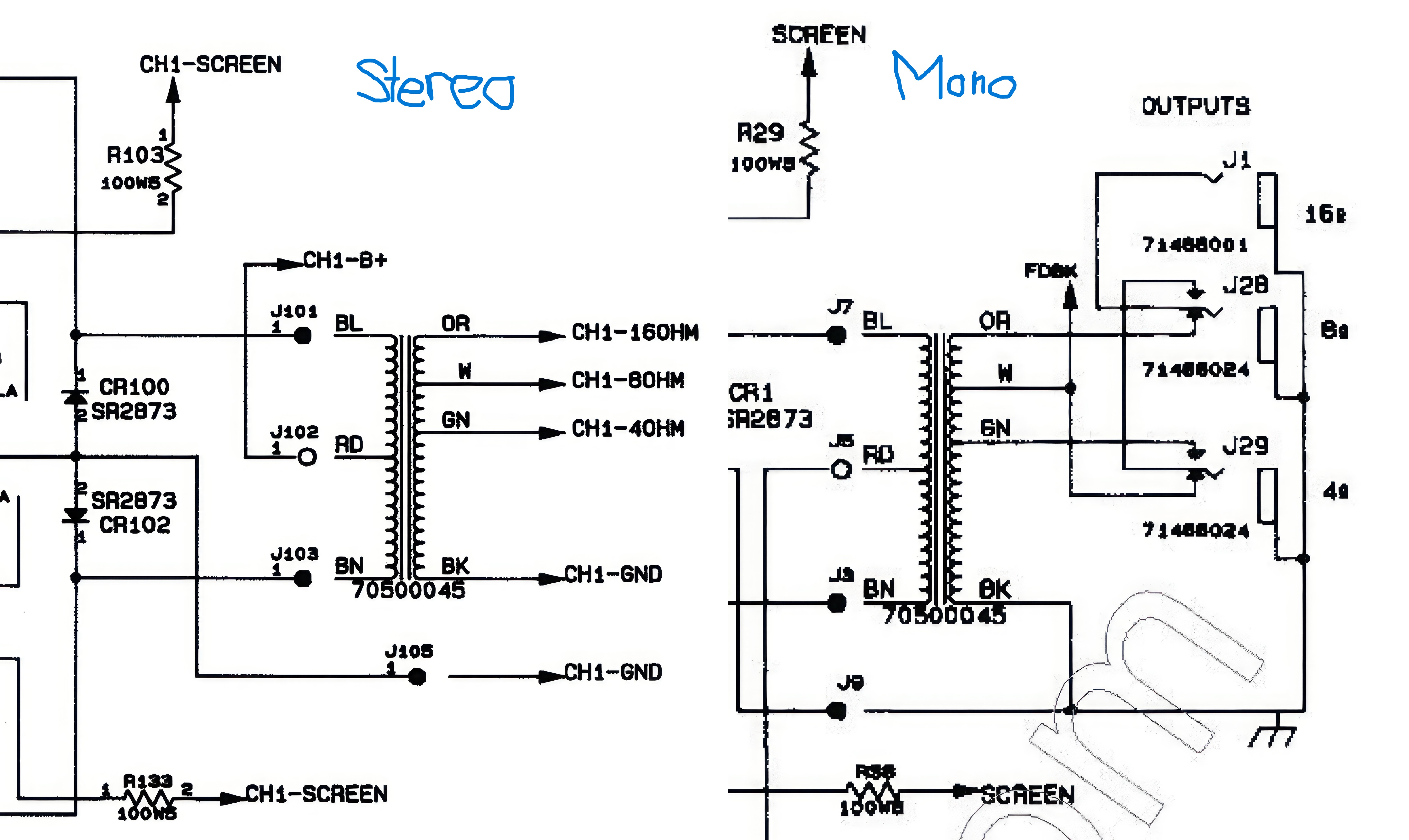
In order to better understand what I did and what the circuit looks like, here are some schematics:
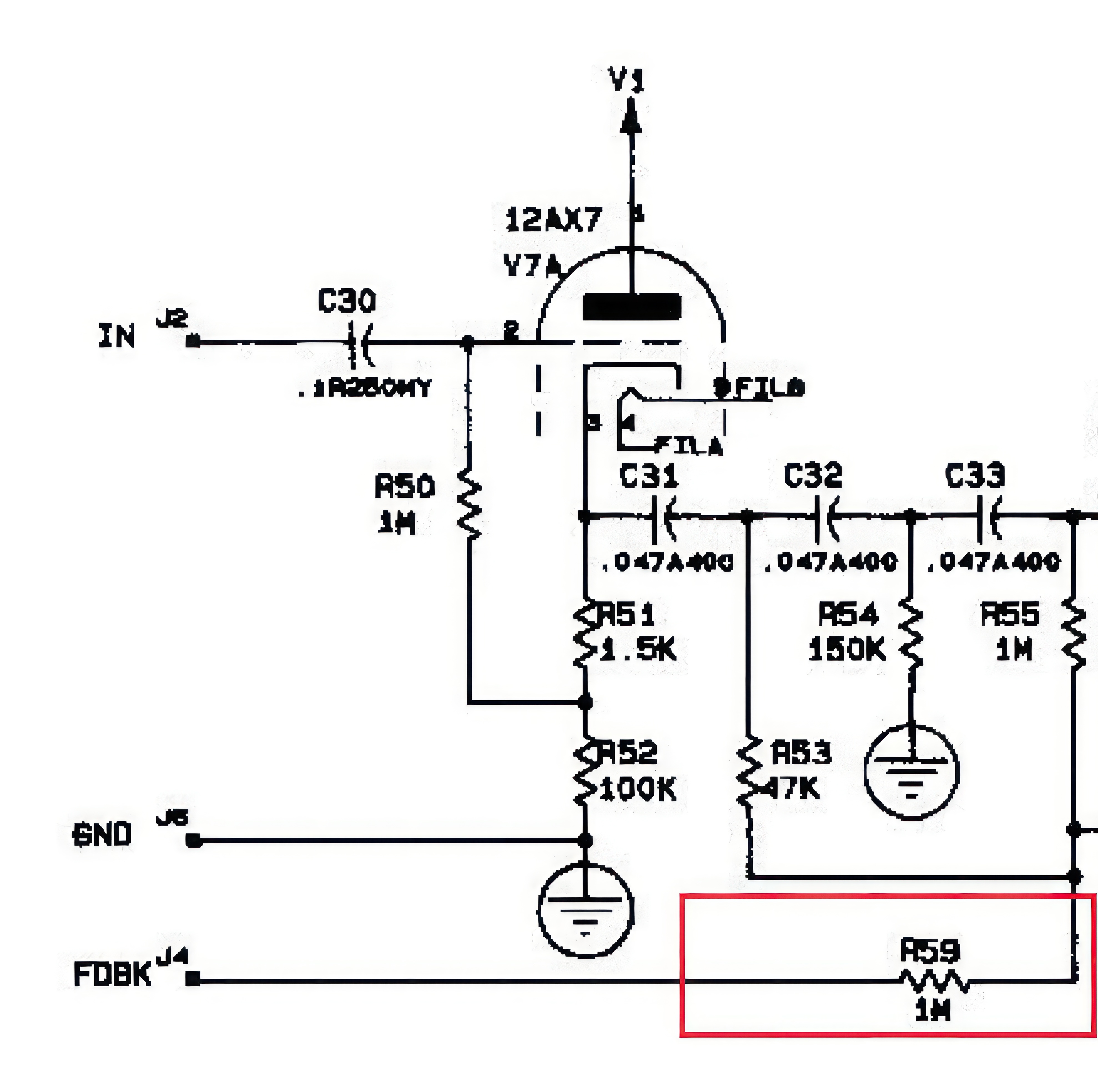
Mono version input stage without presence/resonance circuit, instead there's only a 1 Megaohm resistor which is replaced by the presence/resonance circuit:
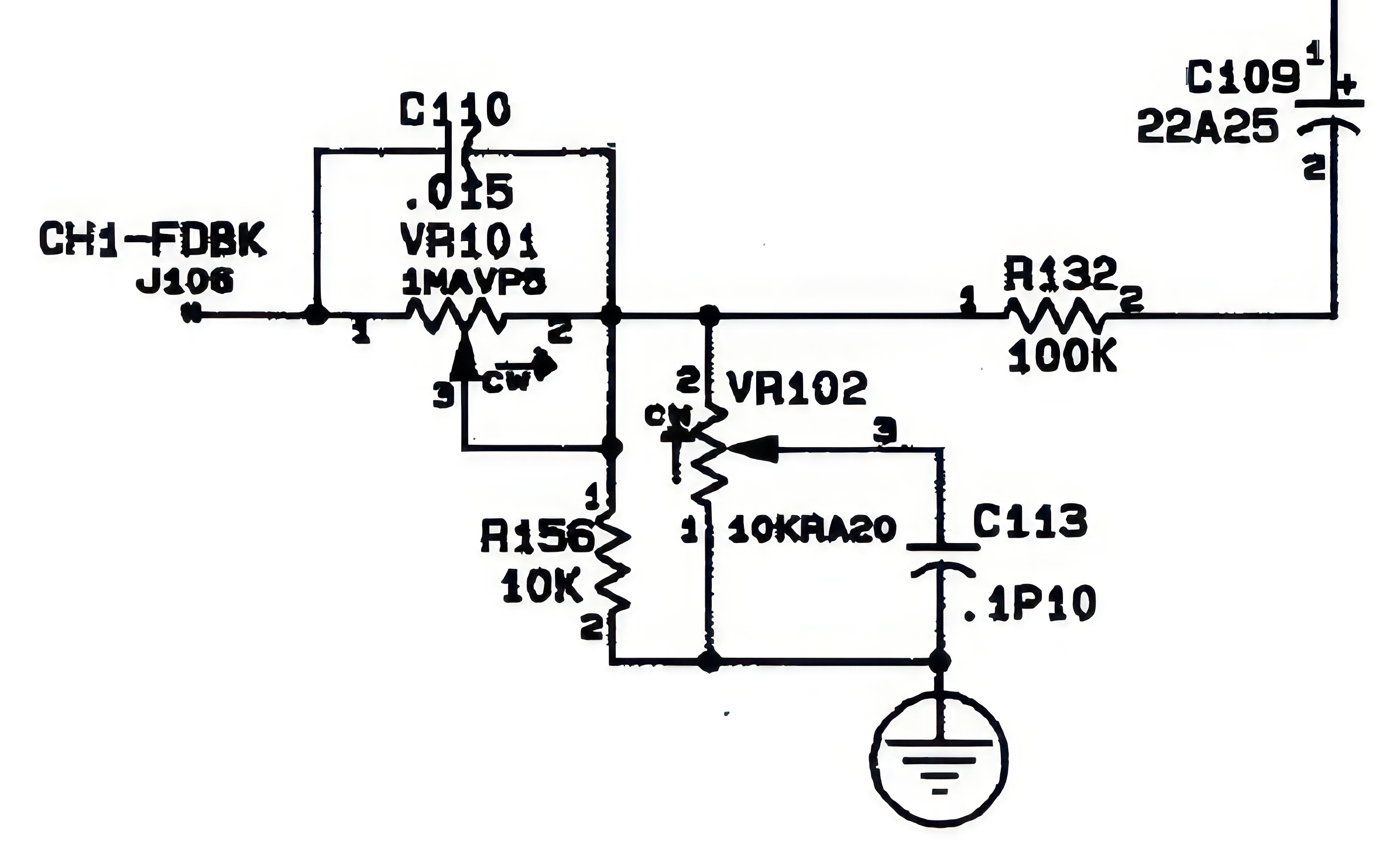
Here's the presence/resonance circuit taken directly from the stereo version:
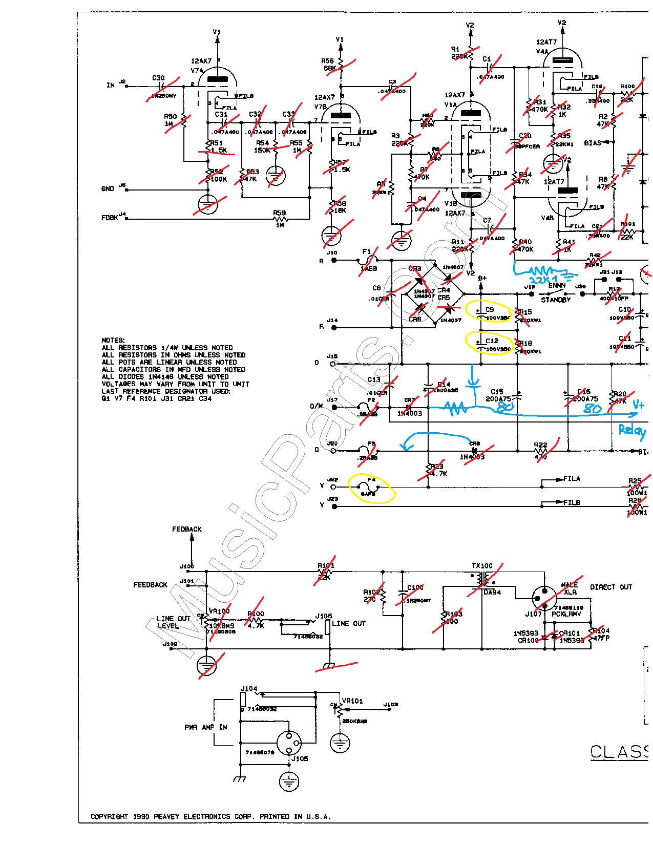
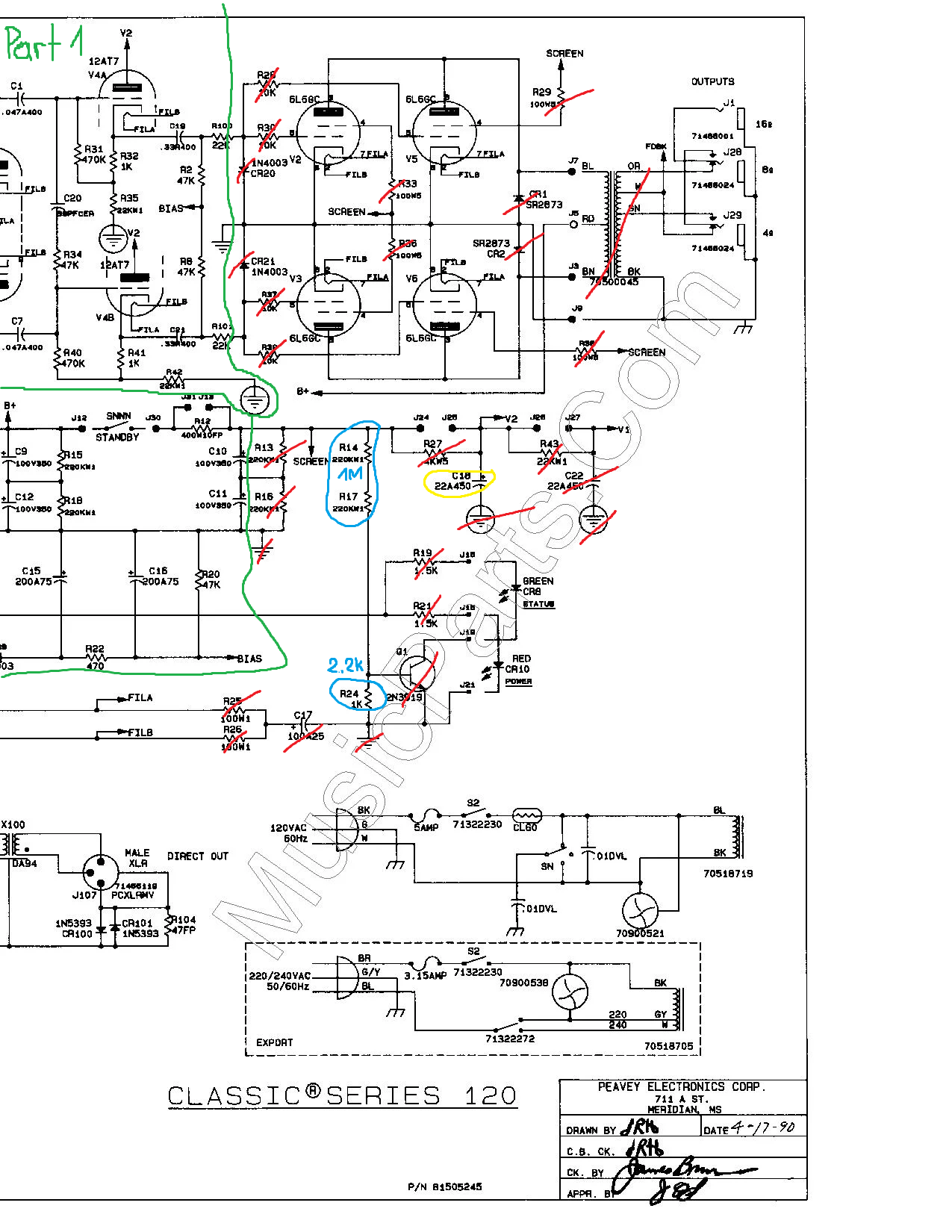
And here's the full mon version schematic which I've compared to the stereo version schematic. Crossed out elements in red are identical between the two versions, blue/yellow denotes either a different component value or additional/omitted components. It has two pages and the first one overlaps quite a bit into the second one, which is why I've outlined it in green on the second page:
Here's also the PDF version of the stereo poweramp:
https://pdfupload.io/docs/3eba0f65
Are the component values purposely false in order to protect the design or should these values theoretically work anyway? Why is it so behaving so weirdly when the resonance potentiometer is below 20% of its range? It's behaving downright dangerously and I really don't know why a circuit that works in unit and doesn't work in the other even though the schematics are extremely similar.
I assumed that the two circuits are identical, one just being two mono blocks in parallel, and I thought that I could just insert the presence/resonance circuit 1:1 into my own mono poweramp, but after inserting the little circuit into the poweramp, I noticed that the resonance control acts very weird when set to the lowest 20% or so of the potentiometer range. There's no sound and the powertubes seem to be overwhelmed as they start to overheat drastically.
How is this possible? Why doesn't the stereo version of the circuit work in the mono version when the two designs are 99% the same. There are some differences near the diode bridge, like added capacitors, different values etc., but that's not the EQ circuit anyway and shouldn't influence the behavior of the resonance control.
In order to better understand what I did and what the circuit looks like, here are some schematics:
Mono version input stage without presence/resonance circuit, instead there's only a 1 Megaohm resistor which is replaced by the presence/resonance circuit:
Here's the presence/resonance circuit taken directly from the stereo version:
And here's the full mon version schematic which I've compared to the stereo version schematic. Crossed out elements in red are identical between the two versions, blue/yellow denotes either a different component value or additional/omitted components. It has two pages and the first one overlaps quite a bit into the second one, which is why I've outlined it in green on the second page:
Here's also the PDF version of the stereo poweramp:
https://pdfupload.io/docs/3eba0f65
Are the component values purposely false in order to protect the design or should these values theoretically work anyway? Why is it so behaving so weirdly when the resonance potentiometer is below 20% of its range? It's behaving downright dangerously and I really don't know why a circuit that works in unit and doesn't work in the other even though the schematics are extremely similar.