Well,
If we're talking about perfboard or Veroboard as it's known over here (also matrix, stripboard etc) you have to specify which type you need. Firstly, there are two matrix sizes- 0.1" and 0.156" IIRC. I haven't seen the 0.156" stuff for years, and it's not much use for anything other than mounting larger non-IC components on. The advantage was that it would plug directly into 0.156" edge connectors...
The 0.1" is the most useful because you can fit transistors and IC's with the minimum of messing about and lead bending.
There are four types of board that I've used:
1. Plain "matrix" board without any copper strips.
2. Classic "veroboard" which has continuous copper strips running parallel across the board.
3. "Tri-pad" which is designed for maximum-density DIL IC mounting- ideal for building up boards of logic circuitry and other digital gubbins.
3. "Padboard" which has a small circular copper pad around each hole, but not electrically connected.
The plain matrix board can be useful to do a quasi-point to point circuit on- you basically bung your component leads through the holes, and solder their leads to eachother, and via small pieces of tinned copper wire. This can be a quick and easy way of knocking up an idea without too much work. Also, because of the lack of parallel copper tracks, your circuit layout can be very direct, although you have to use a lot of plastic sleeving to insulate the leads where they cross.
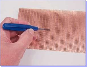
Classic "Veroboard" or "Stripboard" is my favourite. The idea is that you get a handy too like this:
...to cut the copper strips where you need breaks in continuity (or use a 4mm drill bit :wink: ) With a bit of careful forward planning you can create very elegant board layouts very quickly. Here's a handy layout sheet to help with planning:
Veroboard Layout Sheet PDF
The main thing to remember with Veroboard, especially with audio work, is that when you connect a component to a track the signal or voltage appears
all the way along that track- so it makes sense to keep certain paths short by cutting the track at its start and finish. For example, the input terminals to an op-amp connected to a long track which then sits next to a higher-level signal track or an output of +ve polarity w.r.t the input can cause feedback and instability. By shortening the path with a cut, it can reduce any spurious paths. The unused lengths of track can then be bussed with a piece of tinned copper wire to ground to make a sort of ground-plane.
Another way to get stumped is solder blobs across the tracks. The gap between the tracks is quite small, and you have to be pretty careful with solder to stop the joint swamping and "bleeding" over to the next track. This is especially the case with DIL sockets and IC's. To cure it, just run the tip of your iron down and along the track to clear it of the short. Don't forget to cut the tracks running across the board when mounting a DIL IC, e.g. an op-amp. That's a very easy way to slip up!
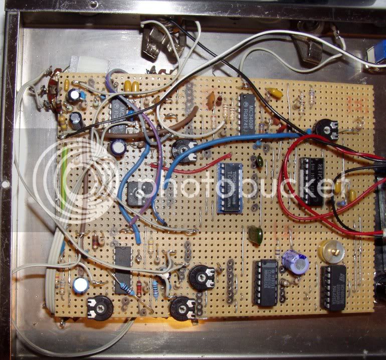
With a bit of practice you can knock up a circuit
extremely quickly. Another good way to work is get one of these prototype blocks:
...and build the circuit on it. When you've got it right, you can transfer it to veroboard directly by copying the cuts and links to the tracks directly. After a bit of practice though, it becomes second nature to just design-as-you-go with stripboard. The advantage of the breadboard plugblock is that you can make mistakes and re-jig things without soldering.
Another problem with veroboard is that you often need quite a few wire links to common adjacent tracks. I use the ends of resistors that I've snipped off, but longer runs need insulated wire. Again, a bit of forward planning can minimise the need for links.
The "padboard" is similar to the point-to-point method, but it allows more support for the components because the leads are actually soldered to a copper pad. You can then tap-solder a wire onto the pad to link to the next junction. This obviously overcomes the problems you encounter with having to make cuts with the spot-face-cutter, but it can take a bit more time having to solder the components in and then add the links.
Anyway, it's a great method of construction for knocking up a quick idea before you design a PC board (and for some projects that become long-term devices too!!)
:green:
Mark


 :shock: