Poor Man's Pultec EQP1-A Build Support Thread

GroupDIY Audio Forum

Help Support GroupDIY Audio Forum:

This site may earn a commission from merchant affiliate links, including eBay, Amazon, and others.
mikeyB said:
Hi Ian - can the poorman make up amp be used with a standard pultec filter network - ie 600ohm.
someone is asking me if i can convert a diy chip amp to a tube output, but want to leave the filter circuit (based on the original) intact.
Will the tube makeup circuit work ok with the original filter impedance?

Thanks in advance :)

Yes, this should be possible. The poor man's tube gain make up (PMTGMU) has a very high input impedance so it will not load the filter. Does the chip amp circuit include the interstage transformer in the original EQP1A or not? Do you have a schematic available?

Cheers

Ian
 
Hi Ian - the circuit does NOT have the interstage transformer - it's built from the diy gyraf filter and the nrgrecording amp stage, and is mounted in the tat purusha case. Output amp is just a 5532 chip but the bottom end doesn't sound right! - a bit thin at extreme settings - i think the opamp isn't up to it!
 
mikeyB said:
Hi Ian - the circuit does NOT have the interstage transformer - it's built from the diy gyraf filter and the nrgrecording amp stage, and is mounted in the tat purusha case. Output amp is just a 5532 chip but the bottom end doesn't sound right! - a bit thin at extreme settings - i think the opamp isn't up to it!

OK, understood. The usual reason for poor low end performance is too low an input impedance . Can you post a link to the nrgrecording amp schematic?

Cheers

Ian
 
I finished to modify my "poor man" EQP1.
My version include the API 325 as gain stage and a mid boost/cut add-on.
The mid add-on use old inductors from old midas PR03 chanelstrips with appropriate caps.
I advise to all poor man EQP1 builder to add this add-on.
Thank Ian for this project, it sound very nice.
 

Attachments

  • IMG_0591.JPG
    IMG_0591.JPG
    91.4 KB
I finished my eq with JFet output stage.But it's unbalanced.I want to make it balanced with in&out transformers.What should i use? Input&output impedances?

Or can get balanced input and output circuit/pcb with NE5532/NE5534? Ebay or...
 
ForthMonkey said:
I finished my eq with JFet output stage.But it's unbalanced.I want to make it balanced with in&out transformers.What should i use? Input&output impedances?

Or can get balanced input and output circuit/pcb with NE5532/NE5534? Ebay or...

For the input transformer you should use a 10K:10K type. The output transformer will depend on the circuit you used for the gain make up. Hard to say without a schematic.

Yes, you can use NE5532/4 for unbalancing and balancing. I think several people have already done this. Alternatively the Dingo Pup PCB made by JLM audio will provide a ready made PCB for just this purpose.

Cheers

Ian
 
ruffrecords said:
ForthMonkey said:
I finished my eq with JFet output stage.But it's unbalanced.I want to make it balanced with in&out transformers.What should i use? Input&output impedances?

Or can get balanced input and output circuit/pcb with NE5532/NE5534? Ebay or...

For the input transformer you should use a 10K:10K type. The output transformer will depend on the circuit you used for the gain make up. Hard to say without a schematic.

Yes, you can use NE5532/4 for unbalancing and balancing. I think several people have already done this. Alternatively the Dingo Pup PCB made by JLM audio will provide a ready made PCB for just this purpose.

Cheers

Ian

Thanks for response! Dingo pup is great! It's one section for in & out right?

BTW i used this gain module.

http://www.diyrecordingequipment.com/wp-content/uploads/2011/02/hamptone_fet_scan.jpg

Gain about 26dB.Is it ok?
 
ForthMonkey said:
Thanks for response! Dingo pup is great! It's one section for in & out right?

As far as I remember the Dingo Pup will do you a balanced to unbalanced at the input amd am unbalanced to balanced at the output.
BTW i used this gain module.

Yes, 26dB is fine. You need an input trimmer to set the gain equal to the loss in the EQ but other than that it should be fine.

Cheers

Ian
 
ruffrecords said:
ForthMonkey said:
Thanks for response! Dingo pup is great! It's one section for in & out right?

As far as I remember the Dingo Pup will do you a balanced to unbalanced at the input amd am unbalanced to balanced at the output.
BTW i used this gain module.

Yes, 26dB is fine. You need an input trimmer to set the gain equal to the loss in the EQ but other than that it should be fine.

Cheers

Ian

Thanks.I want to add out control.

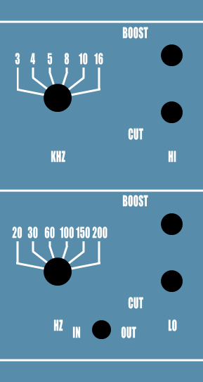
It's my front panel like Mercury EQH-1


And compact.


ForthMonkey said:
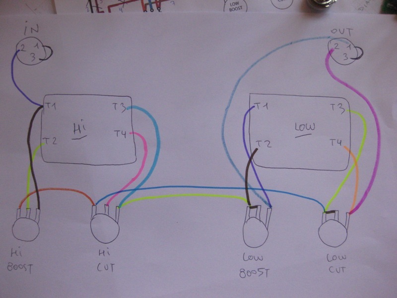
BTW why i'm gettin hum noise when i cut low?

There is no reason why you should provided you screen the signal cables as shown in the documentation. Could you post a picture of your wiring?

Cheers

Ian
 
ruffrecords said:
@ForthMonkey,

What do you connect the output to?

Cheers

Ian

First i connect output to XLR without any circuit like gain stage before building gain stage.Then i connect to gain module but still i'm getting hum noise.

Now i will re-build with new pots.And i think i have to screen low pots like this and connect to case,right?

http://hizliresim.com/emBJ14
 
@ForthMonkey.

The connections to each XLR need to be done with screened cables. Connect the cable screen to pin 3 of the XLR. On the input XLR the screen at the other end of the cable should be left unconnected. On the output XLR the screen should replace the blue wire you have going from the low boost pot to pins 1 and 3 of the XLR. The way you have it wired now you are relyiong on the metal chassis to connect the 0V of the input to the 0V of the output. If you want to run it unbalanced like this then you need to add a wire from pin3 of one XLR to pin 3 of the other XLR.

Cheers

Ian
 
ruffrecords said:
@ForthMonkey.

The connections to each XLR need to be done with screened cables. Connect the cable screen to pin 3 of the XLR. On the input XLR the screen at the other end of the cable should be left unconnected. On the output XLR the screen should replace the blue wire you have going from the low boost pot to pins 1 and 3 of the XLR. The way you have it wired now you are relyiong on the metal chassis to connect the 0V of the input to the 0V of the output. If you want to run it unbalanced like this then you need to add a wire from pin3 of one XLR to pin 3 of the other XLR.

Cheers

Ian

Thanks! Now i understood.
 
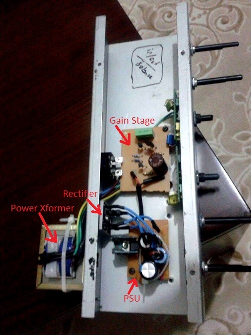
That will probably be OK. The mains inlet is a bit close to the gain make up amp so you must make sure the mains inlet connections are properly insulated. Other than that I think it should be fine.

Cheers

Ian
 
Back
Top