Poor Man's Pultec EQP1-A Build Support Thread

GroupDIY Audio Forum

Help Support GroupDIY Audio Forum:

This site may earn a commission from merchant affiliate links, including eBay, Amazon, and others.
ruffrecords said:
ilfungo said:
I've tried this ,but  I've too much noise..
Pin 3 of xlr must be link to pin 1 and after goes to ground?
Thanks!!!

I am a little condfused. Why are you using XLR connectors? Are you connecting it to balanced gear?


Cheers

Ian
Hi Ian you are right, but, I've just mounted the xlr, and after I've decided to change my project from balanced to unbalanced...
Now I want to use xlr but on unbalanced.
THANKS!!!
 
ilfungo said:
ruffrecords said:
ilfungo said:
I've tried this ,but  I've too much noise..
Pin 3 of xlr must be link to pin 1 and after goes to ground?
Thanks!!!

I am a little condfused. Why are you using XLR connectors? Are you connecting it to balanced gear?


Cheers

Ian
Hi Ian you are right, but, I've just mounted the xlr, and after I've decided to change my project from balanced to unbalanced...
Now I want to use xlr but on unbalanced.
THANKS!!!

OK, in which case just tie pins 1 and 3 together at the connector. You just need to be careful about the balanced gear you drive it with. Some of them do not like having one of their outputs grounded.

Cheers

Ian
 
Hi
I'm building another Poor Man's pultec with IC's Make up gain
schematics attached
Can someone help me with a wirings?
I'm going crazy...
Thanks
 

Attachments

  • INPUT v1.2 SCHEMATIC.pdf
    8.6 KB
output layout


All this documentation come from this forum
Thanks!!!

I've tried all the connections but It doesn't work :(
 

Attachments

  • OUTPUT V1.1 LAYOUT.pdf
    16.7 KB
ilfungo said:
output layout


All this documentation come from this forum
Thanks!!!

I've tried all the connections but It doesn't work :(

You need to connect the output of your input circuit to the input of the EQ. Connect the output of the EQ to the input of your output amplifier. Don't forget the power supply.

Cheers

ian
 
Thanks Ian
from the output of input circuit to EQ I must use a screen cable?
Same from the output of the eq to out circuit?
Thanks
 
Hi Ian
now my new Poor man's pultec whith IC's I/O is working and sound very well ( is one of the cheapest project).
I've only one problem that don't understand:
when I touch the low bost and cut pot I've a hum coming in ( also when go to max with low boost).
I've checked all the connection to ground and seems all good...
Ideas?
Thanks
 
ilfungo said:
Hi Ian
now my new Poor man's pultec whith IC's I/O is working and sound very well ( is one of the cheapest project).
I've only one problem that don't understand:
when I touch the low bost and cut pot I've a hum coming in ( also when go to max with low boost).
I've checked all the connection to ground and seems all good...
Ideas?
Thanks

Which part of the pots did you touch? Which type of pot are you using

The low cut pot is a rather high impedance so you need to make sure the signal cable from the output of the EQ to the gain make up is screened cable. Check out this hook up diagram for more info:

http://www.ianbell.ukfsn.org/EzTubeMixer/docs/PMEQP1A/2-wirescaled.jpeg

Cheers

Ian
 
Thanks Ian
I've used screened cables...
Now i will try to change the type of cable.
I'm using omeg pot.
At very High level ,I listen that if I touch The front panel the hum go away, and also that if i go near the low frequency  pot The hum is very important
Thanks
 
ilfungo said:
Thanks Ian
I've used screened cables...
Now i will try to change the type of cable.
I'm using omeg pot.
At very High level ,I listen that if I touch The front panel the hum go away, and also that if i go near the low frequency  pot The hum is very important
Thanks

Sounds like you have a grounding/screening problem. Check out this diagram agin:

http://www.ianbell.ukfsn.org/EzTubeMixer/docs/PMEQP1A/2-wirescaled.jpeg

Notice that pin 1 of the input and output XLRs are connected directly to the chassis (enclosure) at the XLR. Also note how the mains safety earth is connected to the chassis at the mains inlet and that the power supply 0Vis connected to the chassis at the same point an nowhere else. Make sure the front panel is not insulated from the est of the chassis.

Cheers

Ian
 
Hi again!

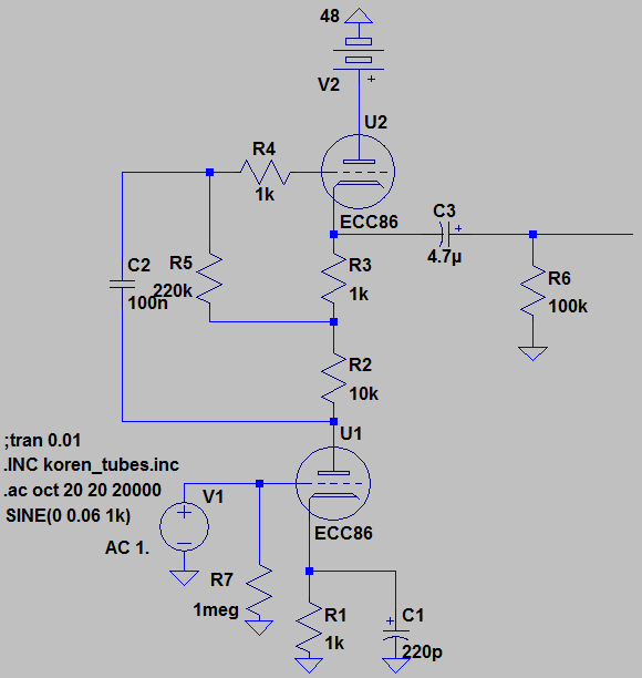
I'm new about tube circuits because of high voltages.But i tried your gain make up circuit in spice with ECC86 (48V) and gain about 22.5 dB.

But i use 0.06V as input voltage because this eq has  24dB gain loss.Am i right?

Can you check my circuit? Can i use this circuit with your gain make up PCB? Only i will change power supply.

A0gMl7.png


EDIT:And with 12AX7 i'm getting about 36dB gain.
 
ForthMonkey said:
Hi again!

I'm new about tube circuits because of high voltages.But i tried your gain make up circuit in spice with ECC86 (48V) and gain about 22.5 dB.

But i use 0.06V as input voltage because this eq has  24dB gain loss.Am i right?

Can you check my circuit? Can i use this circuit with your gain make up PCB? Only i will change power supply.

This is a very interesting tube. Snce you are using the original circuit values, it is probably running at rather too low a current. You will probably need to adjust R1, R2 and R3 to obtain a more suitable operating point.

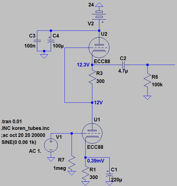
One problem with a mu follower is that R2 drops a lot of HT voltage. When you only have 48V to start with this is probably not a good idea. I would suggest you change it to an SRPP (set R2  and R5 to zero ohms and leave out C2). This will leave about 24V across each tube. From tha data sheet, for 3mA of plate current at 24V you need a negative bias of -1.0V. This means R1 and R3 would need to be 300 ohms. Try those values and see what happens.

Cheers

ian
 
Thanks Ian!

I researched about SRPP and Mu Follower.I'm really new about tube...

ECC86 and ECC88 almost same.I choose ECC88 for this circuit.It has higher gain.

Now with this circuit i'm getting about 26dB gain.Power supply is 24V.I showed voltage drops.

Is this circuit ok?

7VP94N.png
 
I hear a lot of people who are just starting out on tubes say things like ECC88 and ECC86 are almost the same. In fact they are very different. For example the ECC88 has a typical mu of more than 30 but the ECC86 has a mu of 14. The other key factor is that the ECC86 is specifically designed to work off a car battery supply of around 12V but the ECC88 expects  a supply of at least 90v. It is very difficult to be certain of its performance with a 12V supply. You cannot simply use a different tube in a circuit and expect it to work properly without changing values.  You should spend some time studying the data sheets of both tubes until you are clear on this point.

Cheers

Ian
 
ruffrecords said:
I hear a lot of people who are just starting out on tubes say things like ECC88 and ECC86 are almost the same. In fact they are very different. For example the ECC88 has a typical mu of more than 30 but the ECC86 has a mu of 14. The other key factor is that the ECC86 is specifically designed to work off a car battery supply of around 12V but the ECC88 expects  a supply of at least 90v. It is very difficult to be certain of its performance with a 12V supply. You cannot simply use a different tube in a circuit and expect it to work properly without changing values.  You should spend some time studying the data sheets of both tubes until you are clear on this point.

Cheers

Ian

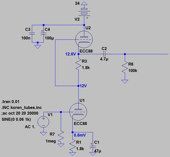
Yes,you're right.I have to spend some time...But when i research about SRPP and Mu follower,i saw a circuit.I tried it with spice.

Q4YXQr.png


Input 0.06V and output 2V

I don't know where i saw but they were using this design.Can i try this with Poorman's Eq?Low voltage and good gain.I can learn something about Mu Follower and SRPP...

And which transformer do you suggest for this circuit? I want to use VTB2281 for output...
 
ForthMonkey said:
I don't know where i saw but they were using this design.Can i try this with Poorman's Eq?Low voltage and good gain.I can learn something about Mu Follower and SRPP...

And which transformer do you suggest for this circuit? I want to use VTB2281 for output...

Which is the whole point. That design probably does work for the application it was designed for but I strongly suspect it was not designed to drive a transformer. You really need a supply voltage of about 200V and a standing current of 5mA to be able to drive a transformer acceptably. The VTB2281 is a good choice of transformer but not for an ECC88 working at 12V plate voltage.

Cheers

Ian
 
ruffrecords said:
ForthMonkey said:
I don't know where i saw but they were using this design.Can i try this with Poorman's Eq?Low voltage and good gain.I can learn something about Mu Follower and SRPP...

And which transformer do you suggest for this circuit? I want to use VTB2281 for output...

Which is the whole point. That design probably does work for the application it was designed for but I strongly suspect it was not designed to drive a transformer. You really need a supply voltage of about 200V and a standing current of 5mA to be able to drive a transformer acceptably. The VTB2281 is a good choice of transformer but not for an ECC88 working at 12V plate voltage.

Cheers

Ian

I see...It can't drive transformer.

OK.I have last question.

Is this possible impedance balancing with this circuit?
 

Latest posts

Back
Top